Updated 2/17/20
Key Search Words: ROBOT, ROBOTICS, ROBOTIC VISION, ARTIFICIAL INTELLIGENCE, AI, GEOBOT

Adding
a home built robotic arm
to
the Geobot for sample collection

|
The Geobot must be able
to secure specimens during its travels and store them for the
return trip. All the mechanical design, shop work with drill
press, band saw, and 3D printer are now finished. The arm is
motorized with expensive Hitec high torque all metal servos,
and each motor can draw over an ampere of current.
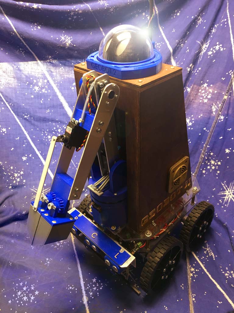
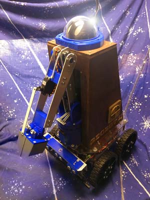
Shown above is the robot
revealing the arm in the folded travel position. It will stay
in this mode even if power is not applied due to spring pressure.
The arm has four degrees of freedom: Rotation at the base, tilt
at the base, elbow, and gripper. The gripper is not articulated
to pivot because of the mode of sample collection does not warrant
this as you will see.
The Hardware
|
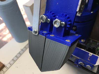
| Lets
start with the collection gripper. Samples will be taken at ground
level of both rock and soil, and a scraping cup like gripper
was created. The cups are geared together so that they open simultaneously
by pulling only on one side with a servo. The servo shaft is
seen here on the left cup. Most importantly, the gripper cups
are replaceable with 4 screws so other designs can be tested. |

|
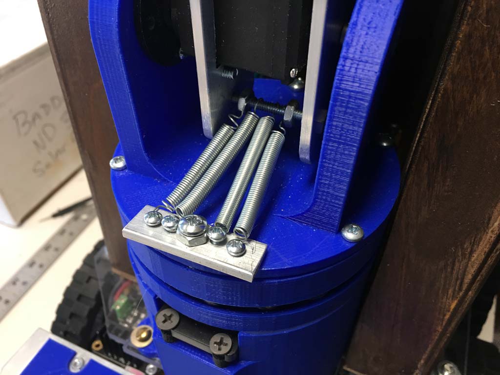
Since all robot
arms are based on cantilevered beams, a opposing force must be
applied to balance the mechanics such that the motors do not
have to lift a heavy lever arm. Small extension springs in the
base are able to perfectly balance the entire weight of the arm,
even when fully extended horizontally.
The azimuthal rotation
base here is quite a bit of design work. More will be detailed
later, but for now I can tell you the weight is carried by dozens
of standard marbles...
|
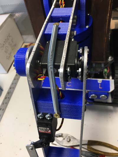
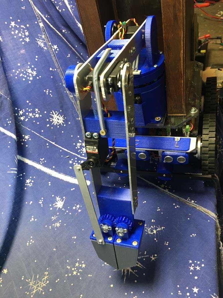
| Elbow
details. A strong motor rotates the fore arm vertically. The
return spring is an extension spring that equalized the loading
on the motor. It allows for a horizontal position on the arm
without stressing the motors too much. The lower servo here is
the lever for the push rod to open and close the gripper cups.
|
|
Previous Uploads on this robot:

1.  Basic concepts and prototype, Base design
2.  Construction of the tower assembly
3.  Connection of base to tower
4.  Base Tower integration
5.  Magnetometer, Sounds, Head Lights and rotation
6.  Code and implementation of the Magnetometer for Navigation
HOME