Outdoor Traversing Autonomous Robot For evaluating outdoor navigation, movements, and functions. Above: The robot base with articulating wheels and lexan platform. Details below. Updated 6/16/18 Key Search Words: ROBOT, ROBOTICS, ROBOTIC VISION, ARTIFICIAL INTELLIGENCE, AI

This robot style has a design that for me has roots dating back 45 years. Yes, I have been designing autonomous robots for that long! Back when I was 14 years old, one design concept that kept reoccurring for me was an outdoor robot with a four wheel mobility base, topped by a rectangular tower like body with a head and mechanical arm. I was determined that someday - When I was considerably more intellectually capable - to actually construct such a fantastic robot. Since then, I have built countless robots but none have actually come to resemble the design in my mind when I was 14. Now it is time.
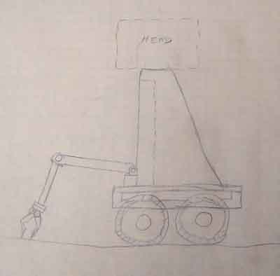
Here is a scan of the original drawing I made when I was 14 to give you the basic concept. (Yes, I have every single drawing of robots I made as a child!)
1973
While quite fanciful in details, the idea was to construct a moving high traction base to enable the robot to drive well outdoors in rocks, grass and weeds. On top a rectangular box like body with slots, readouts, and lights. A frontal articulating arm with gripper allowed grabbing weeds, rocks, etc. Something resembling a soil coring device is on the rear. And most importantly, the robot has a real head! This will be the overall scheme for our new robot. "Mobot I" (what an awful name) will in a sense finally become a reality after 46 years.... Click the thumbnails below for a larger image:
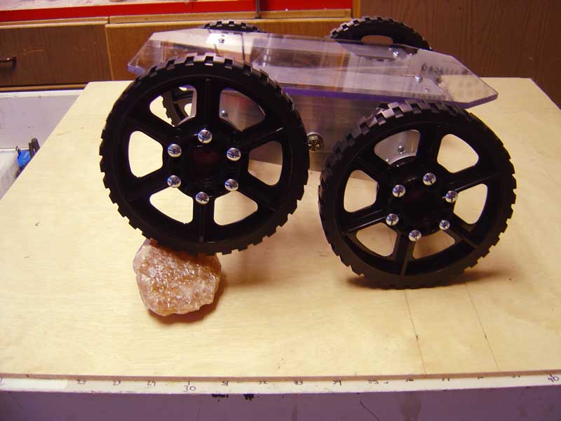
The base must articulate in such a way as to keep all four wheels touching the ground most of the time. To do this, each pair of motors on a side is mounted on a frame that tilts relative to the main platform. This allows the far set of wheels to be flat on the ground and driving the robot forward, while the side closest to you to drive over say a rock up to 2 inches height and still connect with the surface for good traction.
The robot is essentially a foot square and has a lexan top plate to put the rest of the robot on. This is the mobility platform only at this point. The robot steers by what is called "skid steering". This tank like driving technique drives the robot forward by turning all four wheels in one direction. To turn, it rotates on its center by turning one set forward, while the other set goes in reverse. As long as the robots body is fairly wide like here, this works well and is especially suitable for outdoor robots. The rubber coated high traction wheels are six inches in diameter and driven by a quad set of Polulu DC motors with Hall sensor encoders. They are 50 rpm at 12 volts. The fastest this robot will move is about 75 feet in one minute.
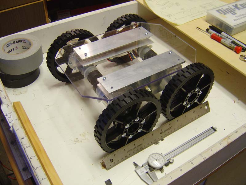
The underside shows the four motors with 100:1 gear reduction mounted on the articulating L channel.
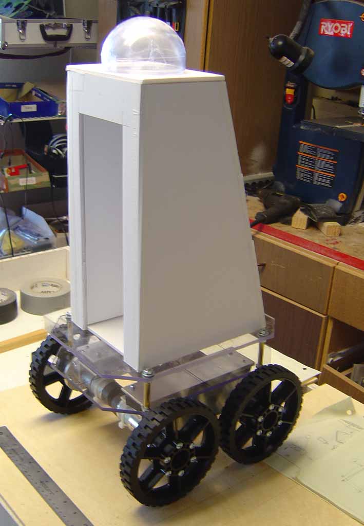
Here is a foamboard mock up to test the dimensions for the tower assembly. This frontal view shows the cut out for the arm to be stowed, with the moveable doors left off. A plastic half dome for a head is shown.
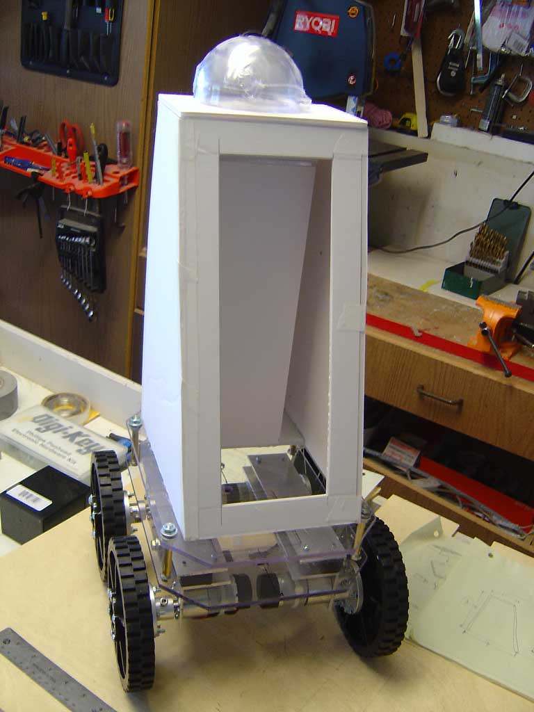
The rear view shows the opening (door off) that will allow access to the inside of the tower where the electronics are to be housed.
This ghostly image is a possible appearance of the robot that will sit on the mobility platform. The only details at this point are a storable articulating arm with 3D printed components, a tapered monolithic tower for a body, and "something" amazing for its head...
Stay tuned!
Previous Uploads on this robot:

NONE YET...