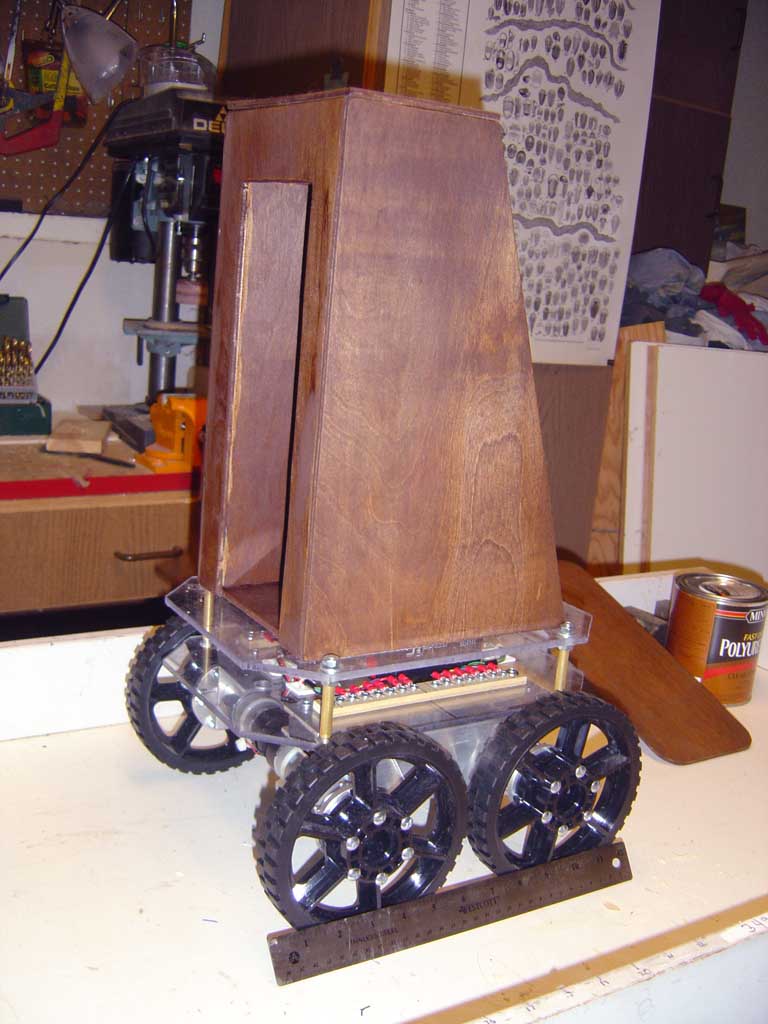
Outdoor Traversing Autonomous Robot For evaluating outdoor navigation, movements, and functions. Above: Test fitting of the stained plywood body on top of the mobility platform. The cutout for the arm is on the left side here. Updated 7/14/18 Key Search Words: ROBOT, ROBOTICS, ROBOTIC VISION, ARTIFICIAL INTELLIGENCE, AI

Here are more images of the construction of the main body of the robot, which is constructed from 5 ply 3/16 sanded finish plywood made for covering floors prior to laying down tiles. Although this is a soft pine like wood, it finishes well and after polyurethane, it will be lightweight and very durable. It is easy to work for holes and mounting sensors and is a perfect scheme for an outdoor forest roving robot.
Click all thumbnails for a larger 1024 x 768 size:
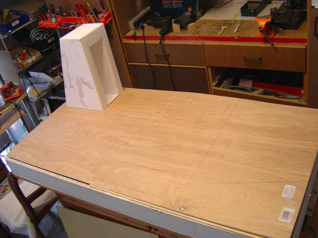
The start of laying out the plywood sheet. The foam core precision model can be seen on the left. The hope is that the plywood version will look the same! One inch gaps were drawn in between parts. This allows the parts to be rough cut on the saw horses with a saber saw, then fine cut on the bandsaw indoors to make a precise cut.
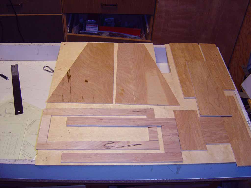
All the parts band sawed out. Its hard to imagine this is 5 ply plywood! It appears to be without voids and cuts cleanly. Some wood filling on the edges will be required.
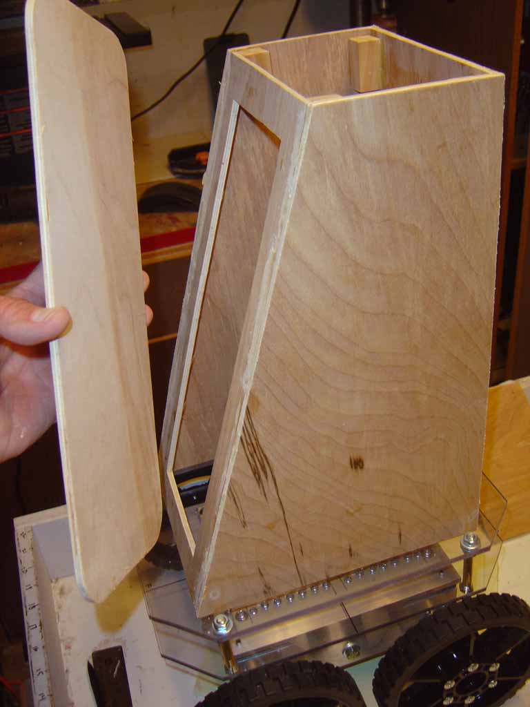
After gluing the parts together in jigs and fixtures to ensure a square profile, the wooden tower is placed upon the robot for the very first time. This is such an exciting moment to see what the robot will look like. Im holding the door for the electronics bay here on the left.
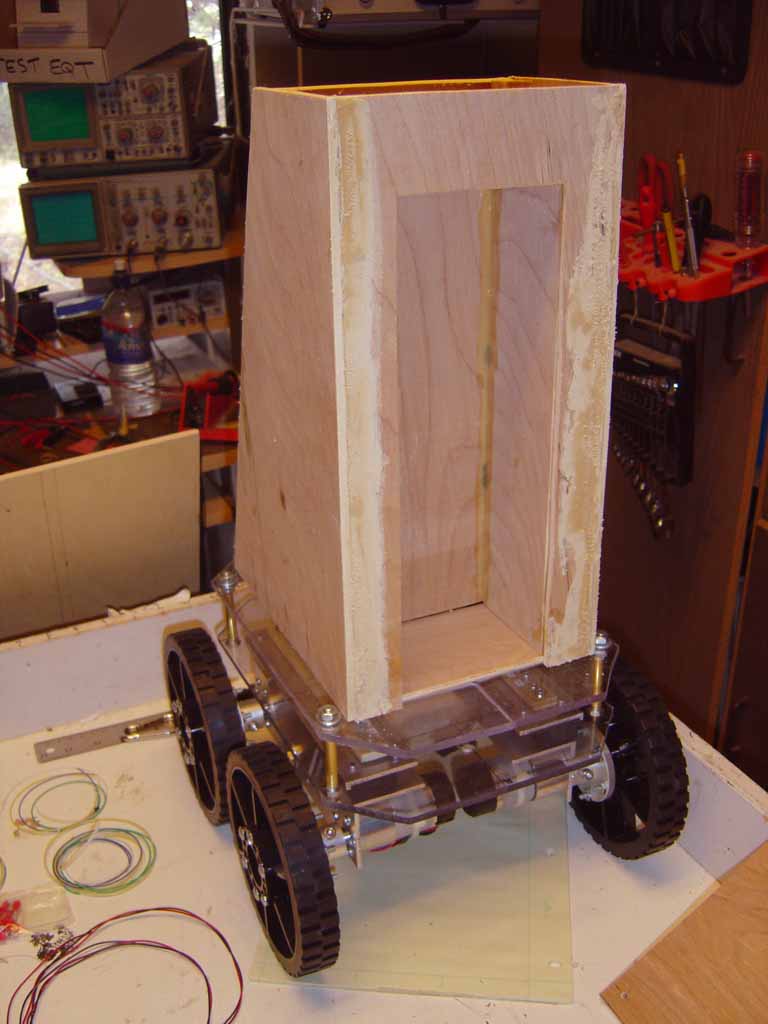
Front view showing the recess for the arm. The robots arm will be folded up and stowed inside this cavity. I may have a set of double doors that open up to let the arm extend.
After filling, sanding and staining, the robots body is nearly done. One more coat of polyurethane will seal it and prevent it from distorting when the humidity changes. The cap is on the top here, and eventually will be the base plate for the robots sensory head. The plate will be removable to allow access to the small cavity under it for sensor electronics. Also, by doing this I will be easy to remove the head for working on it separately. What will the head look like? Stay tuned!
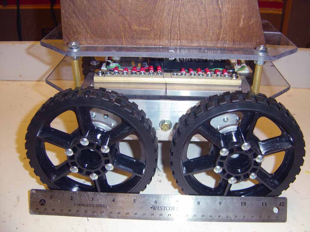
Close up of the drive assembly showing the terminal block on one side I made to hold the red forked terminals that connect to the motors. The black battery is seen inside on the right side.
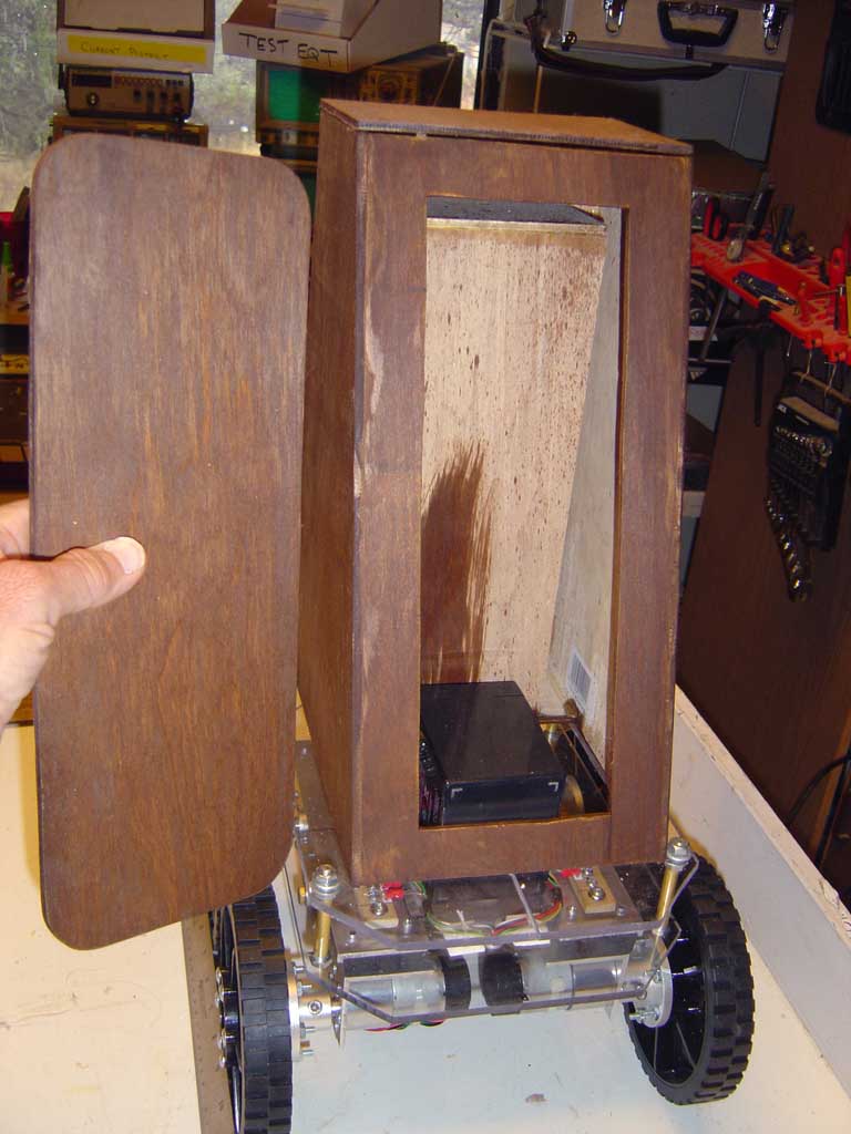
Inside the back door will be the electronics bay. At the bottom is the top third of the battery. You can see I mounted it very low in the robot to keep the center of gravity down near the ground so the robot is much more stable. The top tower weighs really nothing - It is so light to keep the CG low. Even when full of electronics it will be light weight.
NEXT: The plan will be to mount the tower onto the base permanently, and start mounting in the processor boards. Since this is an outdoor robot, sensors must work outside in daylight which precludes any type of IR types, and most tiny low cost lasers. What does work? Acoustical, RF, and vision cameras.
Previous Uploads on this robot:

1.  Basic concepts and prototype, Base design
2.  Initial Hardware construction - 1