Geobot 2 For evaluating outdoor navigation, movements, and sample collection. 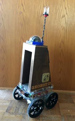
Above: The head rotates, and lights with a dozen different combinations, PID drive is working well, over a dozen robot sound effects are in place, and now we are adding a triple axis magnetometer for navigation.Future additions include sonar navigation, a sample mechanical arm with gripper/scoop. Updated 12/28/19 Key Search Words: ROBOT, ROBOTICS, ROBOTIC VISION, ARTIFICIAL INTELLIGENCE, AI, GEOBOT

In our continuing effort to realize a robot which can remotely collect rock and soil samples, we next examine digital compass navigation. In one of our previous articles here, we detailed how we used a small 18 pin microcontroller to access the I2C data from the Adafruit triple axis magnetometer, we then relay this information serially via RS232 to the UART in the main robot controller. This removes the large burden of overhead which is entailed in these calculations from the magnetometers raw data stream from the main controller.
Introduction
Of primary concern to any outdoor robots tasks is that the robot know which direction it is currently pointing (Current Bearing) and in which direction it must go to reach its destination, way point or final goal (Bearing). One commonly employed tool to accomplish this task is the use of a microcontroller accessible digital compass to provided the Current Bearing of the robot in its environment. Here on the Geobot 2, we employ the Adafruit triple axis magnetometer, which works very well in this machines unrestricted open outdoor environment. Here we will detail how we used this device, in Part 1 of this article on the Geobot's directional navigation.
The Hardware
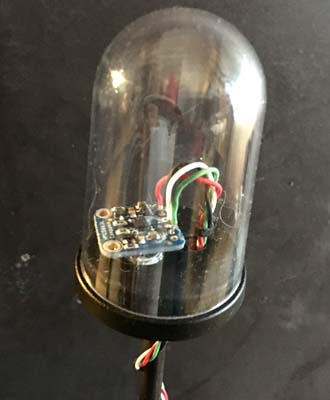
Lets start with a shot of the compass itself, mounted on a 10" mast on the top of the Geobot, far away as possible from the electrical and magnetic interference of the four powerful drive motors below that drive the four wheels. The 1" square PCB is mounted on the base of a cover dome, and a few external components. Only three wires are needed to operate this device: Ground, +5v and the two I2C outputs. The compass is sampled at 50mS intervals using a PIC12F1840 microcontroller.
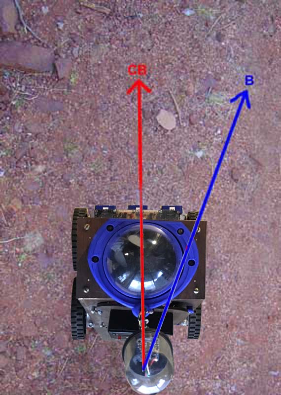
This graphic here demonstrates the basic concept of the two bearing angles we will be working with. First, "B" is the Bearing we wish to go. This number is either derived by calculation and trigonometry or in the case of Geobot's task - it is the first angle it sees as straight ahead when its power is turned on.
"CB" is the current bearing, or where the robot is heading right now. You can see that here in this example, we need to turn to the right about 20 degrees to get back on track to the way we want to be heading. These two numbers will be sufficient to point our robot toward a target, and actually get us very near our destination.
Now lets take a closer look at the two angles, and discuss them in a bit further detail. First, we know that the Bearing angle is of course part of a large circle, that goes from 0 degrees at the top (North) through 90 degrees (East), 180 (South), and 270 (West). We then end up completing our circle at the top again at 359....then 360 which is read as 0 degrees once again.
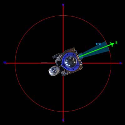
Along with every Bearing angle, there is a Tolerance. This is the small error angle that is considered "close enough" to the angle we wish to go and for the robot if its within this range to consider it to be right on course. This angle varies depending on the terrain, and the accuracy of the drive train. For our robot, with crude four wheel skid steering drive and driving over huge rocks and dips, the angle of +/- 3 degrees was chosen. Any tighter tolerance would not have resulted in a more accurate run and would cause the robot to rock back and forth in an attempt to center on the Bearing.
Next we must consider the math of the correction direction to rotate to get back on coarse. This at first sounds pretty straightforward, but in practice required some careful thinking on our part to get it straight!
The problem is this: If we know the current bearing and the bearing we wish to head, do we turn right or left to make the turn the shortest angular distance possible? We don't want to rotate 359 degrees to the left, when all we had to do is turn 1 degree to the right. Here in this graphic, you can see we are currently going to the upper left at about 300 degrees in direction.
To test to the 45 degree Bearing angle and onward to our goal, its a fairly short turn to the right but we must cross the 0 degree point. On the other hand, if we rotate the much longer direction to the left, we simply count down our degrees from 300 to 45 and were done. In our math before we make a decision on which way to turn, we must first calculate the direction and angular amount. The basic formula is:
1. First calculate absolute distance: Diff = ABS(B-CB) If Diff < 180 then Diff = Ds IF Diff > 180 then Ds = 360 - Diff Shortest Distance = Ds B = Final Bearing CB = Current BearingAlso, since our Tolerance is 2degrees, we know we have to move if Diff > 2.
Some Demonstration Videos:
But which direction do we rotate? There are four cases here.
Case 1: IF Diff < 180 and IF B > CB then ROTATE RIGHT
Case 2: IF Diff < 180 and IF B < CB then ROTATE LEFT
Case 3: IF Diff > 180 and IF B > CB then ROTATE LEFT
Case 4: IF Diff > 180 and IF B < CB then ROTATE RIGHT
Finally, we must calculate at this time the direction for the return trip. Lets say we head out at a bearing of 45 degrees, and after a thousand feet want to turn around and return. The calculation is:
If B < 180 then opposite direction = B + 180
If B >= 180 then opposite direction = b - 180.
Now lets go through an example of the above graphic to illustrate the math. Here we have the following conditions:
CB = 300 and B = 45.
Diff = 255 Ds = 360 - 255 = 105 = Shortest distance. Direction to rotate: B < CB so we rotate RIGHT. Finally, the Opposite direction you are heading is B+180, or 45 + 180 = 225 degrees.
video 1 This first try went pretty well, the tolerance was set to 8 degrees which brought it back close to where it started. The robot drives out 35 feet, then sets its return bearing to reverse its course. It then drives back. You can see it bank slightly to the left or right as it drives to maintain the compass bearing.Note the head movement and eye lights.
This second try in the snow did better than I expected, but you can see I have the linear traveling tolerance a bit too tight because it zig zags slightly on the bearing when set for 3 degrees.While this worked great for dry conditions, the amount of tolerance used when navigating on a striaght line bearing seems to vary with the terrain.
Previous Uploads on this robot:

1.  Basic concepts and prototype, Base design
2.  Construction of the tower assembly
3.  Connection of base to tower
4.  Base Tower integration
5.  Magnetometer, Sounds, Head Lights and rotation