Geobot 2 For evaluating outdoor navigation, movements, and sample collection. Above: The head rotates, lights with a dozen different combinations of lights, PID drive is working well, robot sound effects are in place, and now we are adding a tripple axis magnetometer for navigation. Updated 1/1/19 Key Search Words: ROBOT, ROBOTICS, ROBOTIC VISION, ARTIFICIAL INTELLIGENCE, AI

Here is the latest on the Geobot. The huge project of designing and building a 4 channel motor controller with PID drive for all four motors is done, and awaits full testing on the actual robot. How will it react with all four trying to maintain speed at the same time? We shall see.
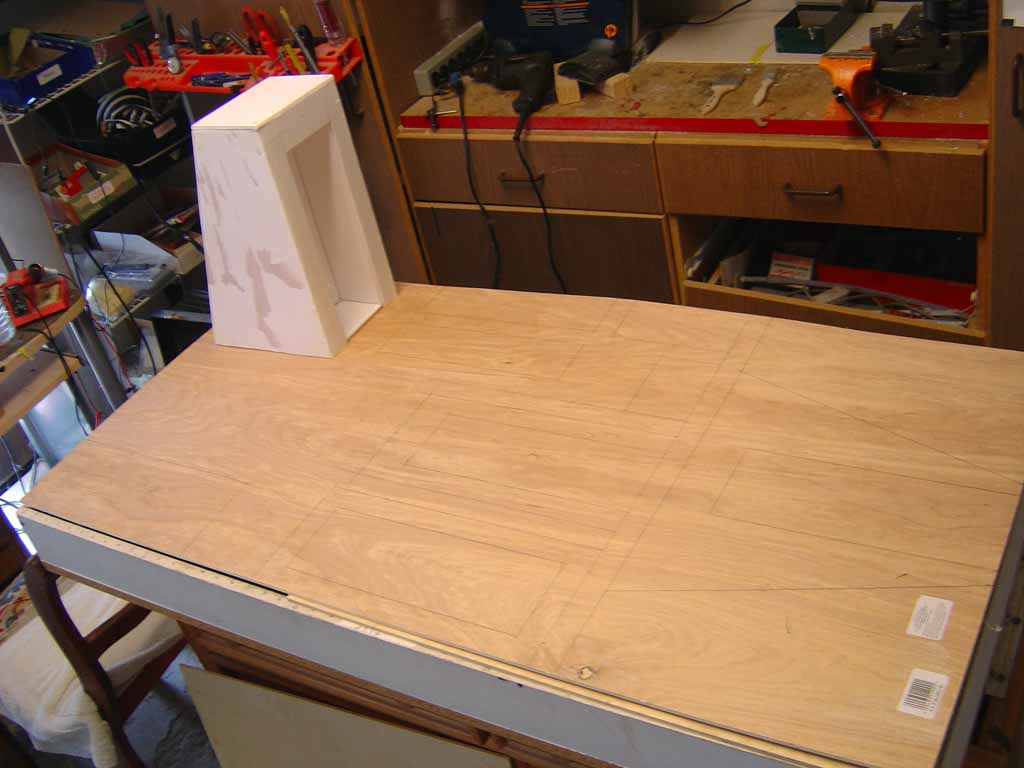
Just before the tower was permanently mated to the motor drive base. You can see the terminal blocks for the motors through the top lexan platform, and the quad motor controller on the front edge. The large black box is the lead acid battery - and rear ballast for the future arm.
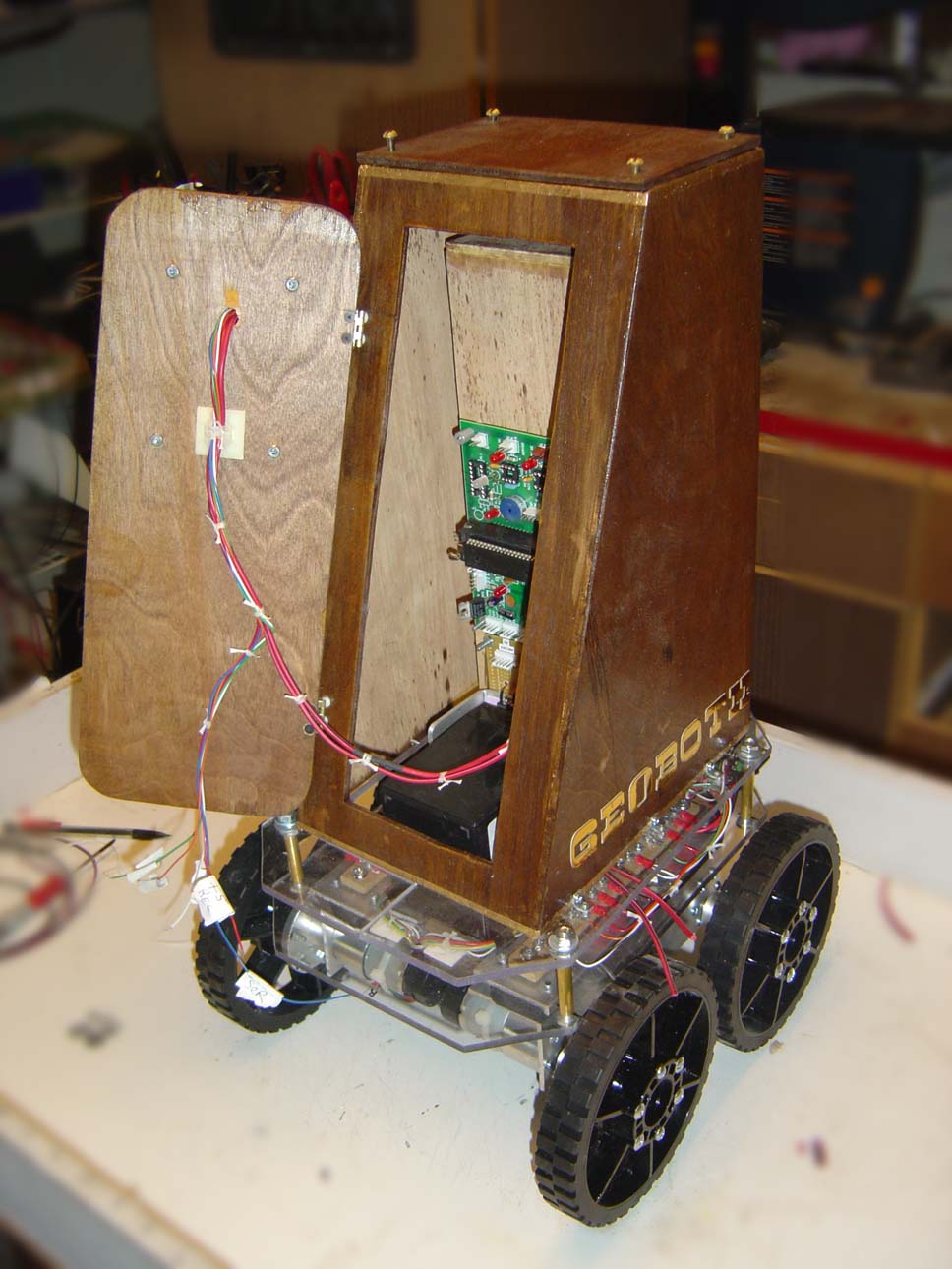
The tower installed and we are starting to wire it in. All the primary power wiring is done - which provides 12v to the motor drivers, and to the 5v regulator power board, with six independent 5v regulators to power future additions!
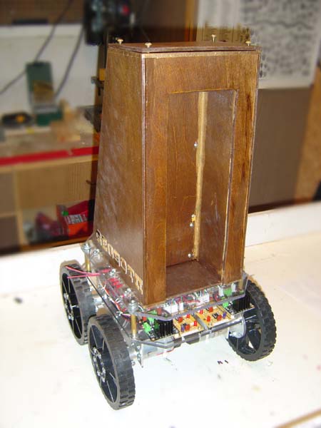
The front side of the tower will eventually house the fold up arm. One version of the gripper is allready done and motorized.
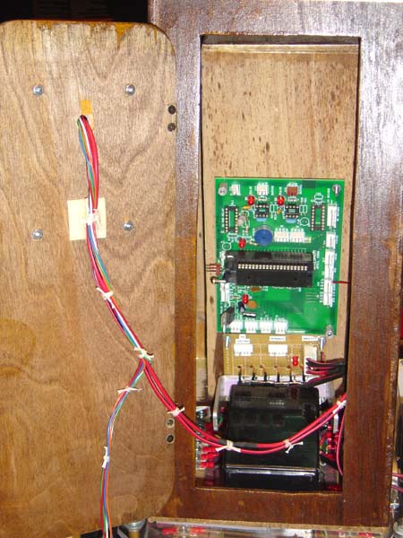
The inside of the tower so far has my custom designed microcontroller robot PCB inside (PIC 16F887 processor) and just below it is the 6 output power regulator board (hand built). Look closely and you can see the big U shaped heat sink that connects the regulators and wraps around the battery.
Previous Uploads on this robot:

1.  Basic concepts and prototype, Base design
2.  Construction of the tower assembly
3.  Connection of base to tower