Incorporating the Triple axis Magnetometer
Once our robot starts to move off of its docking base and on towards its task of watering plants, it will need three major sensors to find its way to the plants and back. The first of which is the current topic of this article, an electronic compass module for direction inside the home, secondly a rolling wheel encoder to determine how far it has actually moved along the floor, and finally a sonar to measure its position off of landmarks to confirm that the robot has indeed reached the various way points in its travel through the house. We have now just finished the compass project with Cbot, and this time we tried something totally new.
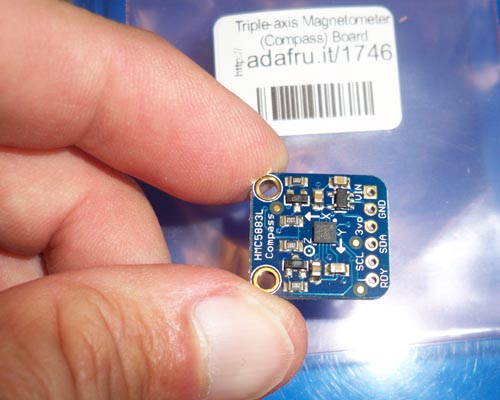
In past robots which used a compass module, we used the Devantech compass module, which costs around $70 or more and came precalibrated for the UK, but worked reasonably well for our location in the world. The calibration procedure was a nightmare, and I never could quite get it to work right. The micro controller read it by measuring a pulse width out of the compass and converting to a compass heading. This worked for several robots, but since then a modern new type of sensor has made its way onto the scene and it was my goal to get one up and running to replace the old and now hard to find former compass. The Adafruit HCL...... module contains a Honeywell triple axis magnetometer with the latest micro engineering technology. The great news is that this small board, which is half the size of the Devantech costs only $9 and has all the level conversion hardware built in for direct hook up to your micro controller. Once I got my version of the code working, the device works very well and easily guides the robot within 2 degrees or better through the halls of the house. I spent a lot of time studying the actual magnetometer data sheet and feel this is a robust device to guide our robot and make several other projects as well. Here are some photos of the new device mounted on the robot.
Left: The tiny Magnetometer break out board. The tiny 3/4" square Adafruit brand triple axis magnetometer break out board. The actual magnetometer is the small black square device in the middle.
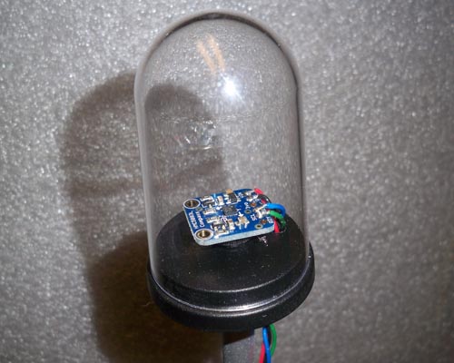
Left: The compass is mounted in a Plexiglas bubble on a non ferrous wooden stalk about 12 inches over the back of the robot. This keeps interference from the robots motors and metal objects on the ground from interfering with the compass bearings. Wires are run down the stalk and then into the robots micro controller boards. The magnetometer uses the I2C interface for communication. (Read: Eye - Squared - C). Compass Mathematics diagrams
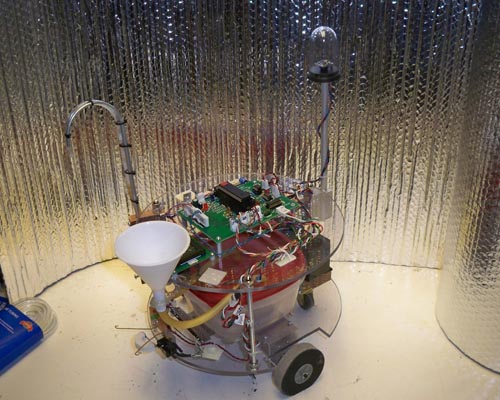
Left: The current state of the robot, with the magnetometer bubble mounted on the rear.
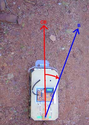
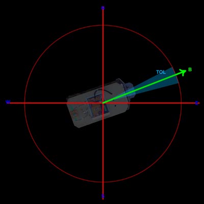
This graphic here demonstrates the basic concept of the two bearing angles we will be working with. First, "B" is the Bearing we wish to go. This number is either derived by calculation and trigonometry or in the case of Geobot's task, it is the first angle it sees as straight ahead when its power is turned on.
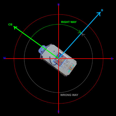
"CB" is the current bearing, or where the robot is heading right now. You can see that here, we need to turn to the right about 20 degrees to get back on track to the way we want to be going. These two numbers will be sufficient to point our bot toward a target, and actually get us very near our destination.
Now lets take a closer look at the two angles, and discuss them in a bit further detail. First, we know that the Bearing angle is of course part of a large circle, that goes from 0 degrees at the top (North) through 90 degrees (East), 180 (South), and 270 (West). We then end up completing our circle at the top again at 359....then 360 which is read as 0 degrees once again.
Along with every Bearing angle, there is a Tolerance. This is the small error angle that is considered "close enough" to the angle we wish to go and for the robot if its within this range to consider it to be right on course. This angle varies depending on the terrain, and the accuracy of the drive train. For our robot, with crude tank tread drive and driving over huge rocks and dips, the angle of +/- 2 degrees was chosen. Any tighter tolerance would not have resulted in a more accurate run.
Next we must consider the math of the correction direction to rotate to get back on coarse. This at first sounds pretty straightforward, but in practice required some careful thinking on our part to get it straight!
The problem is this: If I know my current bearing and the bearing I wish to head, do I turn right or left to make the turn the shortest angular distance possible? We don't want to rotate 359 degrees to the left, when all we had to do is turn 1 degree to the right. Here in this graphic, you can see we are currently going to the upper left at about 300 degrees in direction. To test to the 45 degree Bearing angle and onward to our goal, its a fairly short turn to the right but we must cross the 0 degree point. On the other hand, if we rotate the much longer direction to the left, we simply count down our degrees from 300 to 45 and were done. In our math before we make a decision on which way to turn, we must first calculate the direction and angular amount. The basic formula is:
1. First calculate absolute distance: Diff = ABS(B-CB) If Diff < 180 then Diff = Ds IF Diff > 180 then Ds = 360 - Diff Shortest Distance = Ds B = Final Bearing CB = Current BearingAlso, since our Tolerance is 2degrees, we know we have to move if Diff > 2.
Code Listing (CCS-C)
But which direction do we rotate? There are four cases here.
Case 1: IF Diff < 180 and IF B > CB then ROTATE RIGHT
Case 2: IF Diff < 180 and IF B < CB then ROTATE LEFT
Case 3: IF Diff > 180 and IF B > CB then ROTATE LEFT
Case 4: IF Diff > 180 and IF B < CB then ROTATE RIGHT
Finally, we must calculate at this time the direction for the return trip. Lets say we head out at a bearing of 45 degrees, and after a thousand feet want to turn around and return. The calculation is:
If B < 180 then opposite direction = B + 180
If B >= 180 then opposite direction = b - 180.
Now lets go through an example of the above graphic to illustrate the math. Here we have the following conditions:
CB = 300 and B = 45.
Diff = 255 Ds = 360 - 255 = 105 = Shortest distance. Direction to rotate: B < CB so we rotate RIGHT. Finally, the Opposite direction you are heading is B+180, or 45 + 180 = 225 degrees.
//**************************************************************************** //Chris Schur //Adafruit HMC5883L magnetometer - 16F877A) //Date: 6/16/15 //**************************************************************************** /*Description of this Program: Version 8 - continuous reading version of 7.*/ //I/O Designations --------------------------------------------------- // RB0: Status LED output // RB1: LCD output // RB2: Piezzo Speaker output // RC3: INPUT - SCL - to magnetometer // RC4: INPUT - SDA - to magnetometer //-------------------------------------------------------------------- //Include Files: #include <16F877A.h> #include "math.h" //required for compass //Directives and Defines: #fuses NOPROTECT,HS,NOWDT //xtal is used #use delay(crystal=10MHz) //xtal speed //set up i2c - data, clock pins are here hardware on 877a.part uses slow spec. #use I2C(master, sda=PIN_C4, scl=PIN_C3, slow, FORCE_HW) //HARDWARE IMPLEMENT #use fast_io(ALL) //must define tris below in main when using this // HMC5883 required Registers #define W_DATA 0x3C //Used to perform a Write operation #define R_DATA 0x3D //Used to perform a Read operation #define CON_A 0x00 //Sets up measurement and sampling parameters. #define CON_B 0x01 //Send continuous MeVARurement mode. #define MOD_R 0x02 //Read/Write Register, Selects the operating mode. Default = Single meVARurement #define X_MSB 0x03 //Read Register, Output of X MSB 8-bit value. #define X_LSB 0x04 //Read Register, Output of X LSB 8-bit value. #define Z_MSB 0x05 //Read Register, Output of Z MSB 8-bit value. #define Z_LSB 0x06 //Read Register, Output of Z LSB 8-bit value. #define Y_MSB 0x07 //Read Register, Output of Y MSB 8-bit value. #define Y_LSB 0x08 //Read Register, Output of Y LSB 8-bit value. //for LCD: #use rs232(baud=9600, xmit=Pin_B1, bits=8, parity=N,stream=SERIALNH) //**************************************************************************** //Global Variables: int16 n; //counting var int8 M_data[6]; //Array - 6 units 8 bit Measured datas (compass) int16 Xm=0,Ym=0,Zm=0; //16 bit X,Y,Z variables (compass) float bearing; //final compass reading. //**************************************************************************** //Functions/Subroutines, Prototypes: //for compass only: void hmc5883_write(int add, int data); //write to function int16 hmc5883_read(int add); //Read from function void hmc5883_init(); //Sets up starting conditions void read_reg(); //reads compass registers, calc xyz float calc_heading(); //calculates returns bearing. //For New Haven LCD only: void LCDCLR(); void LCDLN2(); void LCDLN3(); void LCDLN4(); //**************************************************************************** //-- Main Program //**************************************************************************** void main(void) { // Set TRIS I/O directions, define analog inputs, compartors: set_tris_A(0b11111); set_tris_B(0b11001000); set_tris_C(0b11111111); //set both sda and sclk for inputs (float) set_tris_D(0b11111111); set_tris_E(0b111); output_low(Pin_B0); //status off delay_ms(1000); //LCD warmup time //SET BRIGHTNESS OF LCD TO MID RANGE. (DEFAULT = 1) fputc(0xFE,SERIALNH); //Command Prefix fputc(0x53,SERIALNH); //set cursor command fputc(8,SERIALNH); //LCD backlight - 4 is mid 0-8 delay_ms(250); LCDCLR(); delay_ms(250); fprintf(SERIALNH,"CBOT-1"); delay_ms(250); LCDLN2(); fprintf(SERIALNH,"READY"); //start compass single read: ---------------------------------------------- hmc5883_init(); //Initialize compass settings. while(true) { read_reg(); //read compass registers, calc xyz bearing = calc_heading(); //calculates & returns final compass bearing LCDCLR(); delay_ms(10); fprintf(SERIALNH,"H= %f ",bearing); delay_ms(50); } } //niam //********* Functions which have prototypes at top of program **************** //for compass only: void hmc5883_write(int add, int data) { i2c_start(); i2c_write(W_DATA); //0x03 i2c_write(add); i2c_write(data); i2c_stop(); } int16 hmc5883_read(int add) { int retval; i2c_start(); i2c_write(W_DATA); //0x03 i2c_write(add); i2c_start(); i2c_write(R_DATA); //0x3D retval=i2c_read(0); i2c_stop(); return retval; } void hmc5883_init() { hmc5883_write(MOD_R, 0x00); //0x02, 0x00 delay_ms(100); hmc5883_write(CON_A, 0x10); //0x00, 0x10 delay_ms(100); hmc5883_write(CON_B, 0x20); //0x01, 0x20 delay_ms(100); } void read_reg() { //read compass registers //read registers in compass M_data[0]=hmc5883_read(0x04); //Read X (LSB) M_data[1]=hmc5883_read(0x03); //Read X (MSB) M_data[2]=hmc5883_read(0x08); //Read Y (LSB) M_data[3]=hmc5883_read(0x07); //Read Y (MSB) M_data[4]=hmc5883_read(0x06); //Read Z (LSB) M_data[5]=hmc5883_read(0x05); //Read Z (MSB) //Create Word from Highbyte and Lowbyte data: Xm=make16(M_data[1],M_data[0]); Ym=make16(M_data[3],M_data[2]); Zm=make16(M_data[5],M_data[4]); } float calc_heading() { //Calculate using math.h function the bearing. float Heading = atan2((signed int16)Ym,(signed int16)Xm)* 180 / pi + 180; //correct for this equation yielding values 180 off: if (Heading < 180) Heading = Heading + 180; else if (Heading > 180) Heading = Heading - 180; else if (Heading == 180) Heading = 0; return Heading; } //For New Haven LCD only: //Clears LCD Display: void LCDCLR() { fputc(0xFE,SERIALNH); //Command Prefix fputc(0x51,SERIALNH); //Clear screen } //Sets LCD to line 2 start point void LCDLN2() { fputc(0xFE,SERIALNH); //Command Prefix fputc(0x45,SERIALNH); //set cursor command fputc(0x40,SERIALNH); //Set cursor to next line, pos 40 = start line 2 } //Sets LCD to line 3 start point void LCDLN3() { fputc(0xFE,SERIALNH); //Command Prefix fputc(0x45,SERIALNH); //set cursor command fputc(0x14,SERIALNH); //Set cursor to next line, pos 14 = start line 3 } //Sets LCD to line 4 start point void LCDLN4() { fputc(0xFE,SERIALNH); //Command Prefix fputc(0x45,SERIALNH); //set cursor command fputc(0x54,SERIALNH); //Set cursor to next line, pos 54 = start line 4 }BACK TO ROBOT PAGES
Interested in learning more on the development of this robot? Here are previous uploads - LATEST AT THE BOTTOM:
Previous Articles 1. Plant watering sensors 2. Cbot basic concepts and project definition 3. Docking sensor, battery charging and FSM explained 4. Development of the water tank, pump and feed mechanism 5. Development of the reservoir refill system 6. Incorporating the Tripple axis magnetometer for compass navigation