 Cbot
- Plant Maintainence Robot 1
Preliminary
Development Projects
Updated
4/25/15
Key
Search Words: ROBOT, ROBOTICS, ROBOTIC VISION, ARTIFICIAL INTELLIGENCE,
AI

| Here
is an update on the current progress of the Cbot Robot. For the
second half of April, I concentrated on developing the automatic
battery charger and beacon so that we can keep the robot at full
power during the next phase of testing. One of the most important
functions a household robot must do is be able to find the battery
charger, plug itself in, and charge itself up on a daily basis.
For the Plant robot - this means that after it has completed
its watering task every morning, it must return to the charger
and slowly top off the 12v battery for the rest of the day and
into the night. The next morning the Sun comes up - and we do
it all over again. Below you'll find some photos of where we
are at on this and an inside look at how the brains of the robot
will accomplish the entire watering task! |
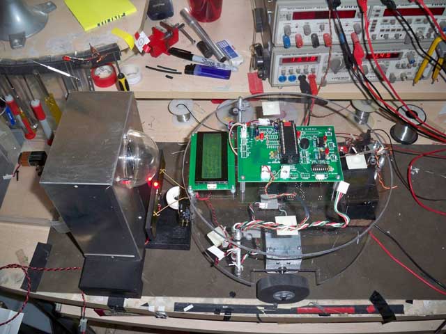 | Left: First
thing was to construct a solid and reliable docking station,
complete with 500 ma battery charger, an adjustable infra red
beacon and two charging plates the robot can drive into to connect
up. Here is a bench test of this in action. The docking station
is on the left and has a red light just above the contacts to
confirm there is voltage present. (13.5v to charge a Gel Cell).
The robot on the right (without its dome) has two "feelers"
made from a Guitar E string that are connecting to the plates.
The battery is able to charge fine WHILE THE ROBOT IS ON. This
allows the robot to just drive up and charge at will. |
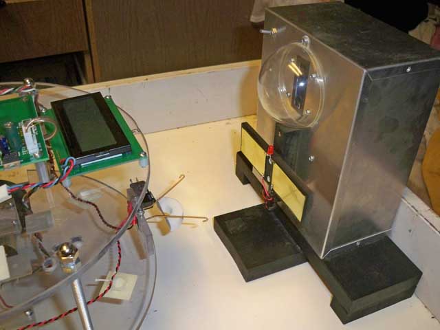 | Here inside
the robot arena, you can see the charger/docking station more
clearly. The electronics are inside the metal box, and the dome
at top has a bar of infrared LED lamps for the robot to home
in on to park itself right on the plates. |
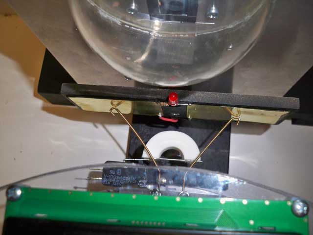
| Viewed
from above, the guitar strings are just touching the plates and
connect directly to the battery terminals in the robot. The white
C shaped foam piece is connected to a lever switch. If the robot
keeps driving towards the plates and does not stop because it
detects no voltage, the switch closes and that will stop the
robot. It is a fail safe. |
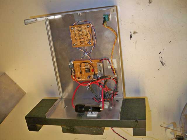 | Inside
the docking beacon. The bottom board is a small 12F629 micro
controller that puts out a constant 38.5 khz signal. This drives
the second board which contains the IR LEDs. |
|
Click to
enlarge!
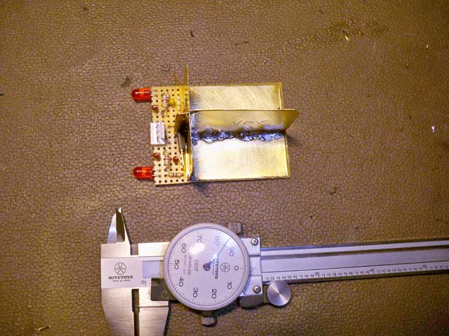
| The
docking beacon detector that is to be installed on the front
of the robot started out like this, three pieces of brass shim
stock soldered to form a vane sensor. Two photo cells that respond
to 38.5 kHz Infrared light are on each side of the vane. by pointing
the vane right at the beacon, both photocells will put out a
signal. If its to the right or left - only one will thus the
robot can home in on the beacon. This all gets painted flat black. |
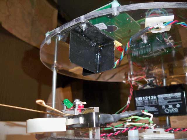
| The
beacon sensor now installed on the underside of the top plate
of the robot. |
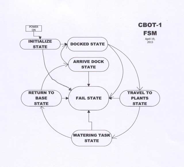 |
A diagram to show
how the robot is currently being programmed to accomplish the
plant watering task. This type of diagram is called a "Finite
State Machine". Each bubble is a separate state the robot
can be in at any time, depending on what its doing. Each state
is simply a separate block of code. The arrows show how it can
jump from one state to another.
The human brain
works in a similar manner. We mentally jump from one mind set
to another all the time, say from walking to driving a car then
talking on the phone. Each task we do is a separate mind state.
Same here. This technique is very powerful in defining the artificial
intelligence of microprocessor controlled systems.
|
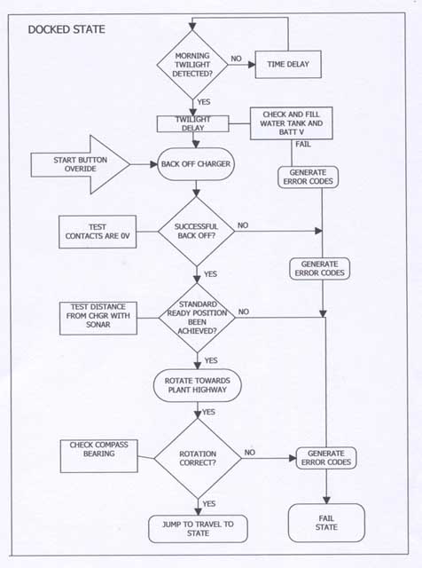 | Here is
an example of whats inside each bubble above. This is for example
the "Docked State" internal flow chart. Each bubble
has its own internal diagram like this and you use it to guide
you as you actually write the program to put into the robots
micro processor. I have not finished ALL of the inner flow charts
yet, but each step of the way is clearly defined for the future! |
BACK TO ROBOT PAGES
 HOME
HOME


HOME