|
The newest version
of my spectrograph for astronomical observation is nearing completion.
Here I detail some of its features, and how it may be used to
generate solar spectra, drift scan spectroheliograph images,
and of course a very nice bench top spectrograph for both viewing
and recording images. It still has a long way to go, but I feel
it has progressed along far enough to starting putting together
some write ups on my progress!
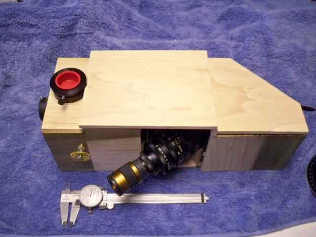
Spectrograph -
Version 3.
This spectrograph
was designed to work both well on the bench, and with very fast
optical systems found in my f/4 astrographs. For solar work,
I will be using an f/6 system with a Baader Herschel Wedge for
basic spectra and drift scan tests. Lets take a look now at the
outside of the box as it sits in my home lab right now. Nothing
is painted black yet! This is a bonus for now, as it is FAR easier
to photograph the individual pieces when they are not nearly
invisible black.
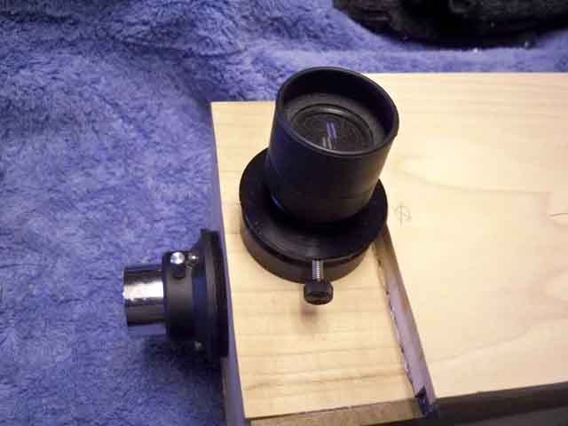
Here it is seen
in visual mode, the eyepice extends toward the lower left, entry
port for light on the left end. There are many hidden details
here. The second focuser on top is of course for an eyepiece
to view the input beam before the slit for object centering.
It is as you can see just over a foot long and about 5 inches
tall.
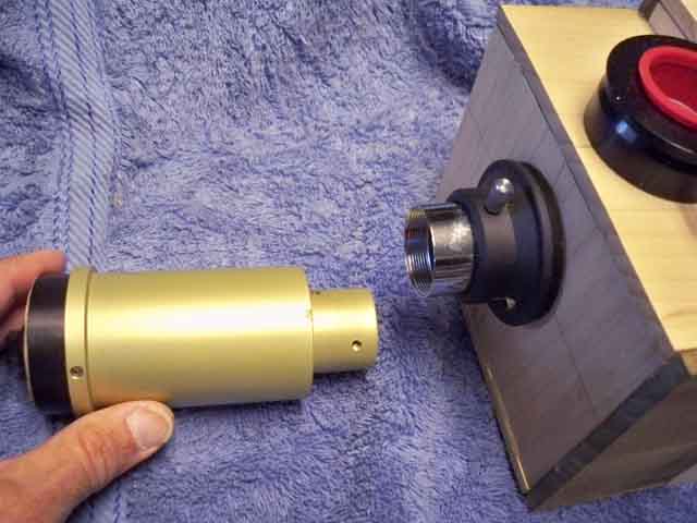
Lets start with
some of the EXTERNAL features so you can get familiar with it.
This is a close up of the input port. It is a 1.25 recepticle
for normally inserting occulars into. But here, I use it two
ways. First, you can see Ive put a 1.25 inch tube into it and
now it can be inserted into any telescope (that can hold its
weight). The other option is the collimating laser - a very essential
item for spectrographs. Everything MUST be absolutely in line
to keep the spectrum flat and centered with a minimum of distortion.
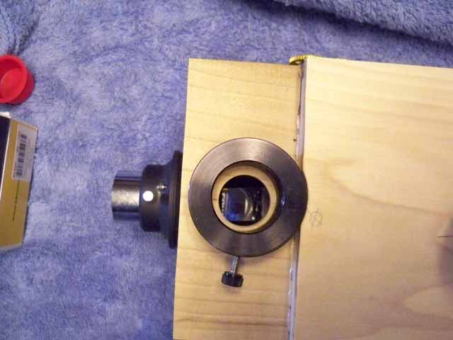
Now lets look at
that second focuser port. You can see down inside it a small
square mirror that reflects the input up here. The eyepiece must
of course be able to focus at the same focal plane as the slit,
so it may have to be a longer FL occular to work.
Now by turning
the brass knob on the outside of the box, we can flip the mirror
up and out of the way - so that the light goes to the hole in
the flip-slit module, and onto the slit itself. The mirror of
course can be locked up!
Now looking down
into the hole, we see the mirror is flipped up and locked in
place - out of the way.
When the mirror
is flipped down, this is the eyepiece in the focuser to view
the image through the entry port. This could be the Sun, or any
celestial object for that matter.
On the other side
of the box is another brass knob. THIS one flips the 25 micron
slit up and down so that you can directly see the image of what
your shooting with the camera or eyepieces with no slit. Normally,
when you take spectra or do a drift scan, it is flipped down.
This entire mechanism which I call the "Flip Slit"
assembly took me the longest to come up with!

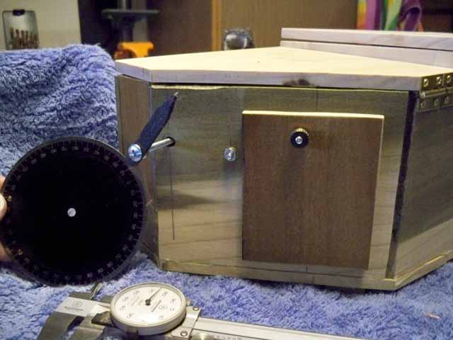
On the back of
the spectrograph is a lever and door. The lever, which rotates
many times around with your finger sets the angle of the internal
diffraction grating allowing you to tune the frequency. A degree
scale I have not installed yet is nearby. The door - An access
hatch to the screws holding the gratings mount so I can swap
them out with other gratings for different amounts of dispersion
depending on what you are imaging. I have a 300, 600, 1200 lines
per mm grating set, all mounted on adjustable bases that I can
swap out.
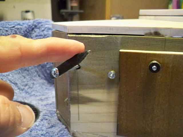
Example of finger
rotation of the tuning lever
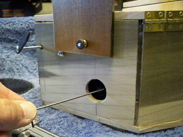
With the door swung
up by loosening a thumb screw lock, I can reach in to the screws
on the bases of the grating mounts. (more on this later)
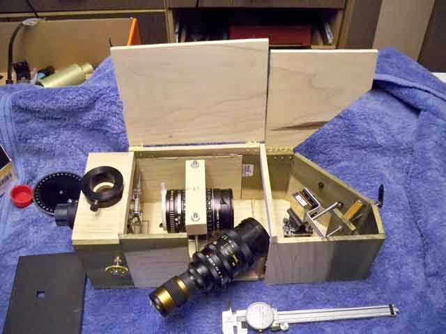
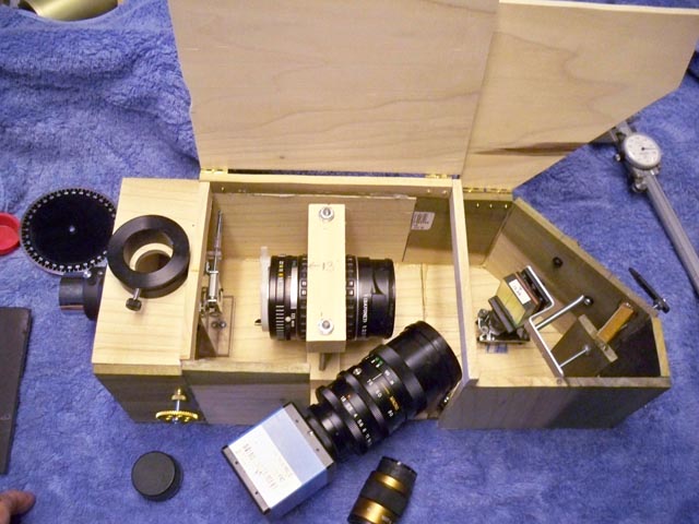
Whats inside the
box:
Both lids open
up on brass hinges, and reveal the inner components. The left
half is the slit, collimator lens (135 mm f/2.8 camera lens),
and the imaging zoom lens with an eyepiece installed for viewing
the solar spectrum. The right side is the grating and mount for
adjustment.
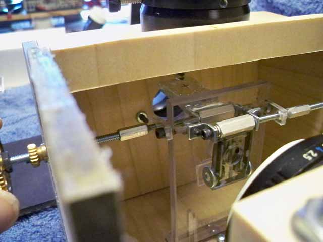
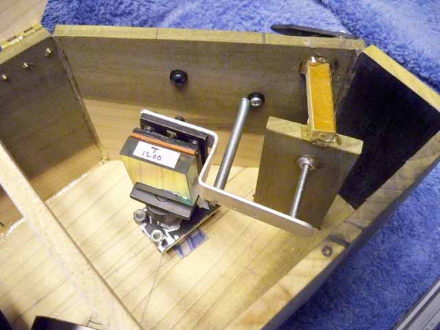
Lets star with
the grating and Flip Slit assembly. It is made of clear lexan,
and of course will all be painted flat black inside when were
done here. But for now, you can see its workings better. The
slit is a home made - under a powerful stereo microscope I may
add - set of pencil sharpener blades mounted on a flap of lexan.
it is attached to the hollow rod above it and the whole affair
can be rotated up with the rod extending to the right here. The
rod coming in from the left, that is connected to the brass knob
flips the 45 degree mirror. Works like a charm.
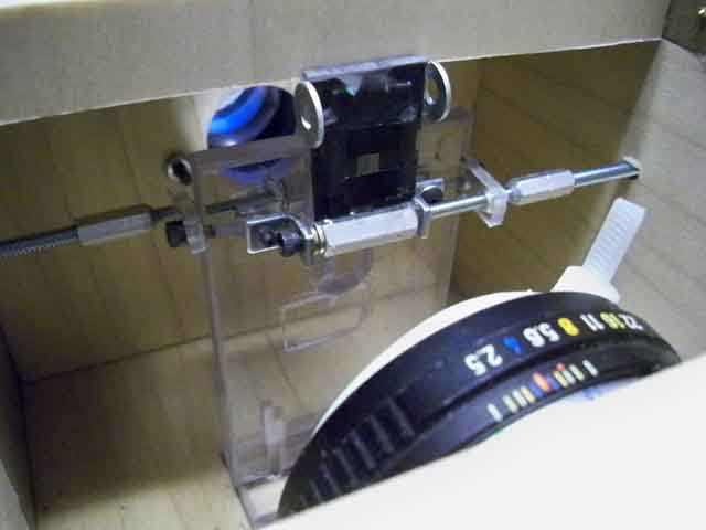
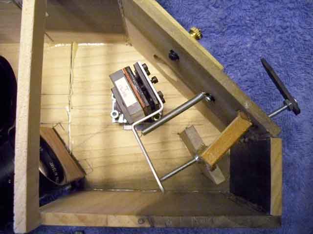
Slit and mirror
flipped up revealing the half inch hole for the light to pass
through for the laser collimation and to be able to actually
see the image as a zero order reflection on the grating with
the camera. NOTE: the slit is masked here to 3mm, but when I
remove the black tape on the ends its a full 10mm. This full
length will be used when using this in spectroheliograph mode.
The solar image with my Zeiss 80mm APO is about 4.8mm.
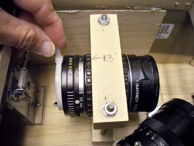
The primary collimator
lens for the slit is a super high quality lens for 35mm film.
It is a Pentax 135mm f/2.8 Super Taukamar, one of the finest
film lenses ever made for astro imaging. Here is has a new life.
The lever (ok its a big tie wrap) seen in my fingers is to vary
the focus of the lens slightly for sharp images from UV to IR.
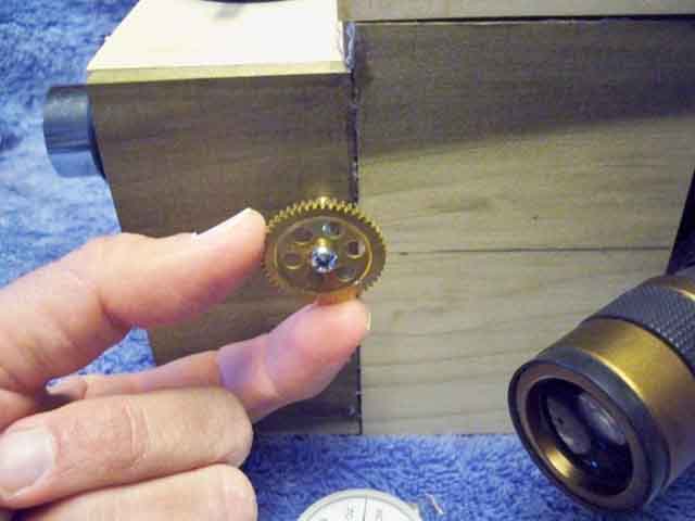
Here is the grating
mount and adjuster. The grating ( 1200) is mounted on an adjustable
tilt plate for collimation and rotation, and the whole affair
is mounted on the shaft of a potentiometer. This will in the
future give out a voltage reading that is proportional to the
frequency of the gratings tilt, and I can read it with a microprocessor
and read out directly in a digital readout the wavelength. Thats
for later. The lever mounted on the back is for tilt, and the
outside lever for tuning is a long screw that pushes the lever,
and the long spring seen here pulls tension on it.
Top view shows
how the external lever adjusts the tilt of the grating in a very
precise manner. That long silver tube like thing is a spring
that is pulling back to keep tension on the push bolt.
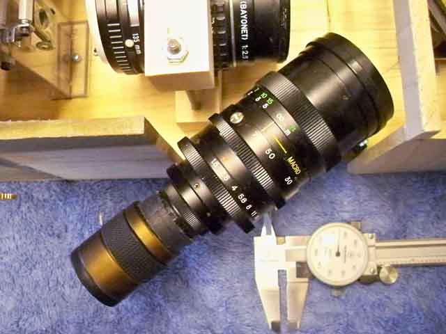
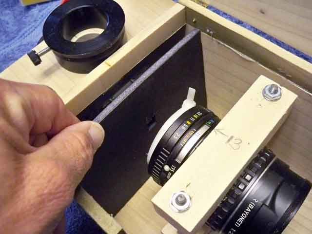
Here is the imaging
lens. It is a 12 - 75mm zoom of superb quality that is very fast
too. I can get the full spectrum in about two shots with the
DMK51 with the 300lpmm grating, and it will take 6 or 7 frames
to see the full spectrum with the 1200. This is shown with a
25mm eyepiece on the back, mounted on a threaded plastic cap
I found that fits the C mount thread. Hot melt glue guns are
great!
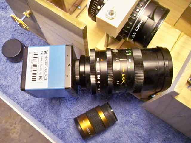
Seen here with
the DMK 51 camera installed, it comes to perfect focus! Spectral
lines are razor sharp.
Until I get the
inside painted black, i use this black foam board with a small
hole in it to get the solar spectrum in the day time. Light still
comes in around the imaging lens, and Im working on a black shroud
for this...
Lids open with
DMK camera installed.
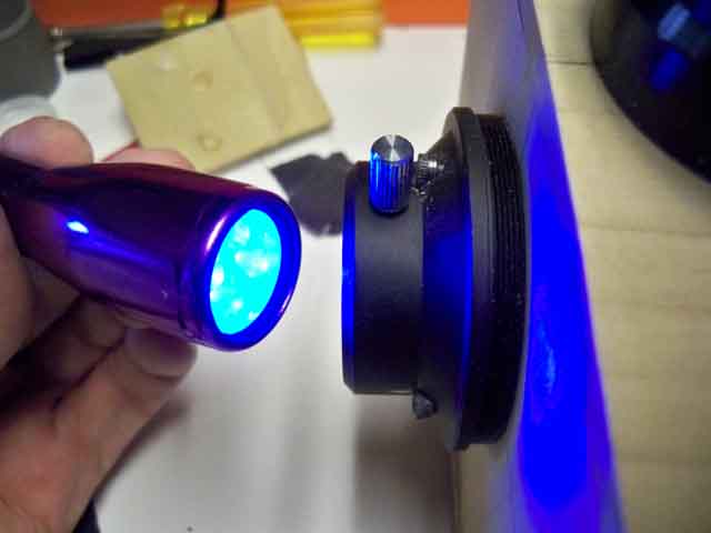
I can use an UV
flashlight which puts out 390-400 nm for testing the calcium
K response:
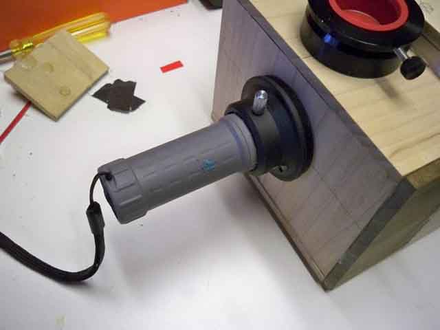
Also a standard
white LED flashlight fits right in the input port and is a great
source for testing the full range of the spectrum visible at
different zoom levels.
Thats what I have
right now, it is a work in progress, but is coming together fast.
First test images soon!
|