|
Robotics
Testing
and optimizing the PID drive
7/04/04
|
 P.A.A.M.I.
|

| crucial to the operation of any
autonomous robot is the drive controller and motor drive electronics.
If you are using hacked servo motors, a motor driver is built
in, but for greatly increased flexibility in the robots speed
and motion, a precise H-bridge type drive with the appropriate
logic is a must. Here we highlight how we built and tested our
motor driver and controller at a level of detail that could be
used as a guide for others even with different processors or
H bridges. |
Click on Thumbnails for large view
Basic Concept of Drive / Electrical Schematic
 | Here is a
electrical block diagram I drew up to illustrate the basic layout
of the drive. The two motor decoders are PIC16F628 uC which has
the code blocked out below. The "Cruise" module, sends
a 9600kb data stream to both decoders for control, and is also
the same PIC. The key component here is the LMD18201 motor amplifier,
which has cruicial logic inside to be able to take the single
unchangeable PWM output from the PIC and a direction and make
it all work seamlessly. We tried the L298, however in light of
the fact you have to add 8 external fast back EMF despikers,
and you must invert the PWM everytime you cross zero and go backwards,
we opted for the all in one package and much more capable LMD
device. |
Programming Block Diagram
 | A quick block
diagram of the method used to move PAAMI about. Although some
may argue that a 1/2 second encoder gate time is slow, it works
fine for interior situations and in the houshold conditons it
is designed for. It was not possible to open these motors up
and gain access to the main shaft. The Sonar is not shown here,
but will be highlighted in a separate article. |
Hardware Implementation
 | Seen here
is the underside, showing the laser printer encoder wheels designed
in Autocad, with 36 sectors for 10 degree resolution. This gives
a useable 25 counts per half second for the robots normal speed.
The optical detector is a Sharp QRB1114 available from digikey
and works superbly, putting out a solid 4v p-p signal into the
LM399 quad compartors for digital shaping. They are about a quarter
of an inch from the disk, and have a converging beam that is
quite insensitive to ambient light due to the IR filteration
on the reciever phototransistor. Another very handy thing about
this device is the slotted middle for sliding it to the optimal
position on a screw or post. |
 | Two 200 rpm
12vcc motors from Jameco for the drive section. they are good
enough to run at a mere 5% duty cycle, however I get very smooth
motion at 10 %. You need a slow speed with those huge 5"
wheels ! |
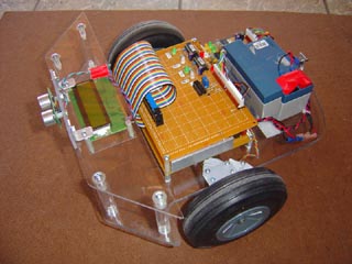
 | The top board
so far consists of two motor decoders (16F628 PIC's), and the
LM399 compartor. The green LEDs are cruicial - they show valid
data on each chip, by confirming the qualifier byte is good at
both ends of the data stream. The Red LEDs are very valuable,
they light only when the PID drive is in the dead band zone,
and thus the motors are running at the requested speed. It usually
takes about 1 - 2 seconds from a standing start. |
 | During
testing, The optical shaft encoder was read every half second,
and displayed on the top line, while the PWM rate which can be
varied from 0 to 255 is shown on the bottom. This way we can
calibrate for a given count speed, what approximate PWM is required.
For the differential term of the PID, we then use about 75% of
the estimated PWM as the starting point from a lookup table for
rapid changes in speed. |
 | The motor
driver board is separate from the rest of the electronics to
keep motor noise and giant switching spikes off the rest of the
electronics. Two gel cells are show, the upper is the 12v at
.8ah battery for the main electronics. The lower battery is a
12v 1.2ah for only the motor. |
Testing and Evaluation
(Non Clickable)
 |
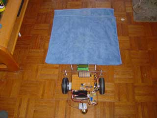
The Rug test. Here
we start the Bot rolling on the smooth floor, then it drives
over a rug which will slow it down normally. But if the PID controller
is working right, it will keep going at a constant speed even
as it exits the rug.
In practice, there is always
a slight delay from impact of rug to a change in the PWM rate,
our goal is to keep this as short as possible - i.e. better than
1 sec.
|
 |
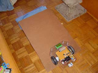
Another torture test
is the steep ramp. As the Bot encounters the steep slope, it
will have to quickly ramp up the PWM to compensate and maintain
a constant speed. The ramp here was one foot tall on the far
end, and the bot drove up the ramp, and leaped off the end onto
the rug, and then continued to drive off at a constant speed!
Here is a short 200k movie of the bot
spinning its wheels up the steep hill.
|
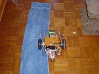
 | A very hard
torture test is to have one wheel on the rug, and one on the
smooth floor. There will always be some pulling toward the left,
but the idea is to minimize it so the bot goes straight. |
 Robotics Main Page
HOME
You are visitor
number since June 17, 2001

FastCounter
by bCentral

Robotics Main Page HOME