 Updated 1/9/05
P.A.A.M.I's
Docking Station and Charging Contacts

|
Last time we discussed the electrical schematics
and circuitry for
building a battery charger for your robot. In this part two of
a series of three articles on self charging robots, we illustrate
our method of making contact with the charger, and a docking
station for your robot to dock with and charge its batteries
when needed.
Contact types
There are three basic ways
to connect your robot to a charger, first the robot basically
plugs itself in to a standard connector arrangement, and second
a frictional contact array or spring loaded separate contacts.
A third method, which is seldom used is to use charging coils
in a base and robot to inductively connect the robot to the charger.
While the first method seems to be the obvious choice, the accuracy
required to plug two connectors together makes it a difficult
task. The third method involves large and heavy inductive coils
and is generally less suitable for home robots. We therefore
found that the second method is the best for around the home
and is easy to make.
Contact plates
This method works with
a wide range of misalignment , and is simple to construct. We
tried spring loaded copper contacts, assorted guitar springs,
pressure plates, contact fingers, carbon brushes, and even rolling
metal wheels with metal axles. Each has its merit, but none was
more successful and reliable for us than the copper plate and
spring ball method. The idea is to have either the robot or base
have a two plate flat copper or brass board, in which the spring
loaded balls slide onto. The problem with putting a copper plate
on the front of a robot such as is used in the Octobot, is that
that valuable real estate on the front is taken up, where we
would normally put IR sensors and bumpers. The same would be
true with spring loaded contacts on the front of the bot. The
answer then is to put the copper plate on the BOTTOM of the robot,
and have it slide over the spring loaded balls. That way your
not dragging the contacts around the house on the robot, picking
up socks, and cat toys on the connections.
But does it work?
Using this arrangement,
we have had 95 percent success on the first attempt when docking,
and 100 percent on the second pass. When the robot fails to connect
for some reason, it simple backs up and goes forward again and
gets it on the second try. Our next article will detail the programming
for docking, charging and escaping the charger in more detail.
Now on to the hardware photos and descriptions!
|
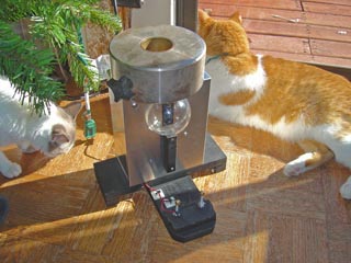 | The docking
/ feeding station. The T shaped base contains the contacts and
is stable with a three point support. Above it is the metal electronics
box, containing the beacon array, 18vdc 1.6A power supply used
by the robots charger, and the bumper to prevent impact with
the clear beacon dome. On the top is a 20 pound steel weight
to keep the charger in place. (Almost looks like a counterweight
for a telescope, doesn't it?) The beacon sends a beam with 5
high power IR LEDs that is modulated at 38.5 kHz. The beam width
is narrower than the docking acceptance angle for the robot -
this is critical to insure a successful docking. |
| Contact arrangement.
Two brass balls from the hardware store used in lamp shades were
drilled out (they are tapped for #8) to press fit onto the expansion
springs. These are the type that are all squeezed shut and you
pull on them to expand them like a rubber band. They sit about
1/8 inch above the bottom of the robot and will drag across the
copper plates underneath the bot. | 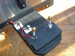 |
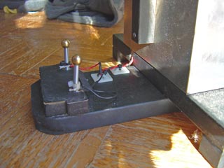 | Side view.
To connect the wires to the springs, we soldered the wires first
to brass shim stock, and wrapped it around the base of the spring.
Then a tie wrap secures it to the spring. The springs can be
bent over 90 degrees and be even run over by the robot with out
any problem of springing back. And believe me, your robot WILL
run over them from time to time! |
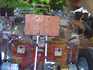
| The underside
of PAAMI shows the copper plate on the front for contact electrically.
The left side is ground, and the right side is for the +18vdc.
Note the barrier between them that has no connection for safety.
The balls obviously must not contact both and short them so that
why the barrier was put in. The width is about 3 inches and depth
about 2 inches - plenty of "runway" for the balls and
to stop the rolling robot in time. | 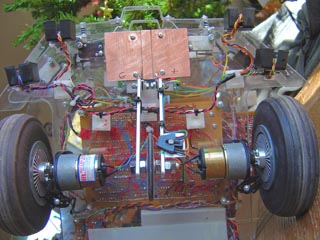 |
 | Close up
of the plates. I used 4-40 pan heads to secure it to the lexan,
and the balls just bounce off them when these hit. |
| Looking at
the front of the robot, just underneath to show the copper plates
are flush with the bottom lexan. Of course the drive motors and
stasis sensor wheel hang below too. | 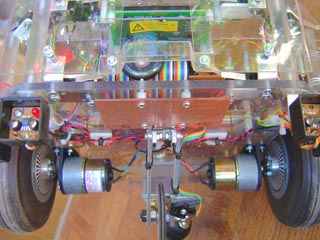 |
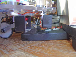 | Not an easy
shot to take, You can see the balls on the springs leaning forward
as they contact the underside of the robots copper plates. The
black boxes contain the IR proximity sensors (IS417 type) |
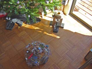
| PAAMI cruising
along in an area of the kitchen where the robot seems to visit
most frequently. The charger is just in the sun. IF she is hungry
(low battery) AND the beacon sensor sees the beacon THEN the
charge level in the 8 layer priority arbitration architecture
kicks in and causes the docking behavior. | 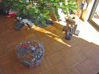 |
 | First, she
rotates toward the beacon using the beacon sensor. By rotating
rather than banking the turn, we don't have to worry about hitting
anything and therefore the charge processor subsumption level
does not have to look at the IR prox or bumpers. |
| Heading directly
toward the charger. It may make a correction or two in direction
along the way, but it generally heads right for the beacon within
about an inch accuracy. | 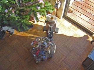 |
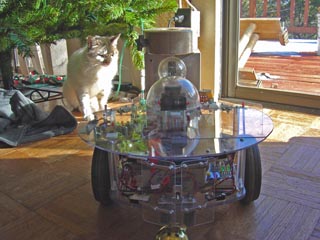 | Looking over
the top of the bot as it heads directly for the beacon in the
dome on the feeding station. The beacon sensor is also in a dome on the top of the robot to protect
it from the evil coffee table shelf. It has a guitar string bumper
in front of it as well. T'Pring watches as the robot nears the
charger. |
| DOCKED! The robot sees the voltage
on its copper plates, then stops, shuts down everything except
the charge processor and soaks up the energy. Takes bout an hour,
then it turns systems back on, backs up and does a charger escape
maneuver to clear the charger. Although the beacon sensor will
see the charger many times in the hour or so It runs, it will
simply ignore it until it has a low battery. Ahh, the wonders
of Priority Arbitration Architecture ! | 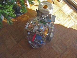 |
MPG move Clips with sound of the robot in action docking.
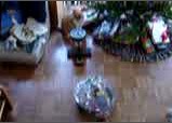 Still from actual Movie
| 385
Kb - for standard modem connections. In these movies, taken with
my Sony P10 digital camera, the sound reveals the robots response
to the charger. First, you hear the "Pip.....Pip" of
the sonar of the level 0 subsumption level scanning the area
ahead for obstacles. The when the robot sees the charger, it
makes the "Happy Sound" and homes in on it. |
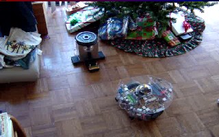 Still from actual Movie - half sized
| 5.3
Mb - for high bandwidth connections. You'll like this one. |
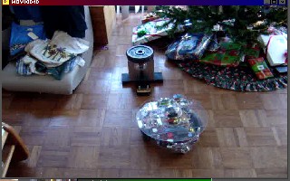 Still from actual Movie - half sized Still from actual Movie - half sized | 6.9 Mb -
for high bandwidth connections. Shows the bot hunting for the
beacon on the way in. |
HOME
You are visitor
number since June 17, 2001

FastCounter
by bCentral