
Extensively bench testing PAAMI's battery charger circuit.
Introduction Nearly all home robots run on batteries, either non-rechargeable alkalines, or rechargeables such as NiMh, NiCad, or Lead Acid Gel cells. Because of their low cost, high current capacities, and relative ease of charging, the common choice is to use the durable but a bit heavy lead acid Gel cells for keeping our robots running. This article is the result of researching this type of power source, and how we can adapt them to a self charging robot that can continue on autonomously for many months, if not years by itself. Also here we will be dealing with some battery charging basics, and in later articles move onto making the hardware to allow your robot to literally "feed" itself.
Figure 1
The Basic Charger Concept With Gel cells, the rules are simple: Don't charge the battery too quickly, and stop charging before you cause damage. Gel cells - as do all batteries, have a rated Ampere Hours. That's about how long a battery will put out the specified useful voltage at one amp of current. So for example, a standard 7 Ah battery will drop in voltage from about 12.5 (full charge) to about 10 in about 7 hours under a load of 1 amp. The ampere hour rating varies a bit with load, you will find that the greater the load, the less the measured ampere hour rating becomes. For example
pull 2 amps out of that same battery, and you might not get the 3.5 hours you expect. Internal battery resistance is the culprit here. But its a good guideline. When a battery is exhausted, usually below 8v, you need to charge it, since most robots run on 5v logic and have a 2v overhead on the regulators.
Current Limiting
Two parameters define how to charge a lead acid battery. First is the maximum current allowed as to not overheat and destroy the battery, and second, the maximum charging voltage the battery is allowed to obtain. As for charging current, the golden rule is not to exceed 1/10 the ampere hour rating of the battery. So as the rule goes, for our 7 Ah battery - charge at 700 milliamps, and it will take somewhere around 10 hours. I don't know about you, but I don't need my robot sitting on a battery charger for 10 hours but only running around for 1 hour before it has to go back to the charger. This "rule" can be bent a bit, without hurting most batteries. For the most part, you can charge the battery at 1/2 the Ah rating, or here 3.5 amps maximum. If the battery gets excessively warm, you'll have to back down a bit, although my Power Sonic Gels Cells didn't even hardly get warm. A simple current limited charger is in Figure 1. Although crude, it limits the charge set by the resistance R, which is typically under 10 ohms and a minimum of 10w or so. But a problem with this circuit is that when a battery is dead or low, its internal resistance is low, causing it to draw lots of current. That where the limit R comes in. As the battery charges, its resistance increases to nearly infinity. So it draws almost nothing as it nears the final point and presents an expotential charging curve. (Here at 13.8v) So the net effect is that the charger works fast in the beginning, but slows to a snails pace at the end, taking DAYS to fully charge the battery. Not the best way - but it works.
Now the Voltage Limit
So you may say, charge a 12v battery with 12v, right? Nope. The voltage on any charger must be at least 1 volt more than the battery your charging. Thats why your car battery charger puts out 14v or so. This allows the current to flow right up to the last millivolt of the final charge voltage limit. There is some discussion as to what that number should be, but goes something like this: The maximum voltage we should charge gel cells to is about 13.8v. After that, if we want to trickle charge a battery to maintain its charge from slowly dropping from internal battery resistance, we can hold it safely at 13.4v without internal degradation from sulfation. Our goal then in a robot charging system will be to achieve full 13.8v and then disconnect the charger from the battery at that point. A signal will then be sent to the robot that the batteries are full, and for it to undock from the charger. Here are some more circuits.
Constant Current Chargers
Figure 2
Figure 2 above is the next step in the right direction on a robotics charger. By adding an adjustable regulator such as the LM350 or LM317 in the configuration above, we get a constant current source. This circuit does the following: A constant current output, at the batteries present voltage appears on the B+ terminal. Adjusting R1 will set the current level per the equation listed above. So what it does is if you set for say 500ma with R1, even if shorted a current meter will always read 500ma max. When connected to a battery, an interesting thing happens. As more and more voltage is applied from the 18v power supply to keep the current constant, the battery voltage will rise as fast as possible without damaging the battery. All the way up to the magic 13.8 volt mark, you will be providing a maximum current to the battery to charge it. So in only an hour or two, we can ramp the charge up on a gel cell. But theres a catch - you must stop the charging at 13.8v, or it will keep going until it reaches about 16.5 v, which is the regulators overhead drop from the 18v input. That of course will trash the battery! So we simply have to monitor the battery during charge, and stop it at the appropriate time with a comparator circuit or analog input on a microprocessor.
Figure 3
A Better Charger.
Figure 3 at the left is another modification to the above circuit. By adding the transistor and pot to the circuit, we can do two very important things. First, the final 13.8 output limit can be set. The current is still set by R1. This charger goes full bore up until it reaches the 13.8v, then Q1 kicks in and slows the charge to
very small trickle. So we get the best of both worlds here, a current limit, and a final stop voltage, AND a trickle charge. This charger will work great for any SINGLE battery. But if you have multiple batteries such as one for your drive motor and one for your micro electronics to separate the noise spikes from the motor that can get into the electronics, this circuit cannot be tied to a common ground with another circuit of the same type such as most dual battery systems are with a common ground, then you will have to use the system in figure 2.
What we used for our Robot PAAMI
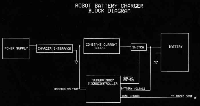
Because of the grounding, we choose the circuit in figure 2, and created a dual charger controlled by a single inexpensive microcontroller, the PIC12F675. This part has up to 4 A/D inputs, and with 1k of program memory, is perfect for the task. Below is a block diagram of one "channel" of our dual charger. The charger "interface" is the contacts on the robot that will connect to the DC power supply on the charger base that the robot docks with when it is "hungry". The circuit is simple to understand and is the same constant current source illustrated above. Here's how it works in real life with the robot:
When the robot docks with its docking station, the connection is made on the charger interface connector. The microcontroller sees the voltage jump and after testing it several times for validity, makes the done status line go HI, and the robots multiprocessor architecture stops the robot, and shuts down all power except to the charge processors. The supervisory micro turns on the relay switch, and charging starts. It constantly monitors the battery voltage, and when it reaches the predetermined value - in this case 13.8v, the status line is toggled at 10hz. Why? because if for some reason the docking disconnects during charging accidentally, the status line will go low, and the robot will attempt to redock. The toggling of the same line allows a third state to be used to signal a charging done condition. Pretty cool, ay?
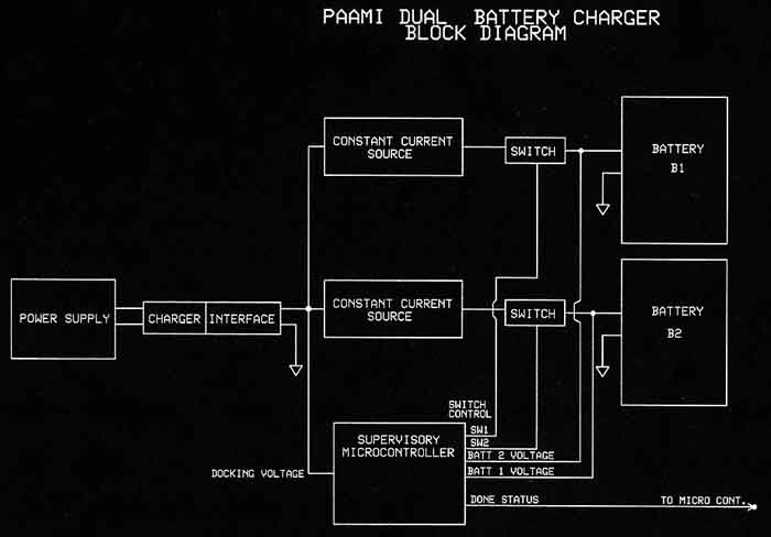
Paami's Dual charger
Because the 12F675 has six lines, I was just able to add control to the second battery's charger. It was a simple extension of the above circuit, but twice as many parts. I'm getting a lot of bang for the buck (actually 89 cents) on this processor - I cant say enough about its versatility for quick circuits. You'll see me use this device and the 12F629, which has no A/Ds but is even cheaper.
Performance in actual use
The charger works great, and I've had no mishaps so far. The logic for both chargers is that the status line flashes at 10Hz only if both batteries are charged. One battery usually gets charged first, then the processor waits for the second one to catch up. It doesn't matter which one is done first. The robot stops on contact with the charger in about a quarter of an inch, and shuts down. As an interesting experiment, I have intentionally disconnected the plug from the wall outlet while it was charging, and every time the robot wakes up within seconds and backs up and attempts to re-connect. The robot stays on the charger for just under an hour. Then it roams for an hour before it reconnects to the charger. I have my currents set for 250mA and 500mA for the two different sized batteries in the system.
Photo Gallery
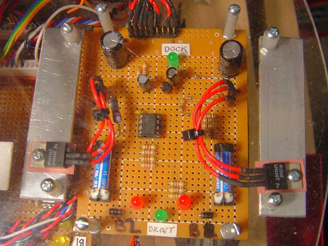
Above: Here is a photograph of the dual charger as installed in PAAMI. We are looking through her clear lexan lid where it is attached to the underside. The board is 3 x 4 inches in size, and flanked by two aluminum strips used as heat sinks for the regulators. The blue cylinders are the relays used to turn off the charge current for each battery when the time comes. In the center is the PIC12F675 micro controller that is the charge supervisor. Indicator LED's show the current battery charge status, docking status, and the "DKOUT" lamp is on the charge status line that indicates the docking test has been validated. When it flashes at 10Hz, both batteries are charged and the leve 7 priority takes over in the robot - and escapes from the charger.