|
We next advance upwards to this next level
of visual complexity by using a scanning method for image production
reminiscent of the old NASA Viking landers. These Mars landers
used a mirror to scan the scene in both a horizontal and vertical
format to generate a full 2 dimensional image that was digitized
and sent to Earth back in the mid 70's. For our new project,
we will be evolving our visual method to the level of the first
most primitive animals on Earth that could form crude images
of their surroundings for an advantage in survival and feeding.
Let me explain this in more detail. Small slug like animals which
were amongst the most advanced creatures to exist at their time
some 600 million years ago in the seas were able to at best use
two eye spots that did not form images to get information on
their environments. That was the focus of the last project, the
Rotifer program. As the requirements for vision increased, and
the first hard shelled animals appeared, a much more complex
mosaic type of vision evolved. Here, the eye spots started splitting
into groups, and formed clear lenses over them to enhance their
light sensitivity in dark sea bottom environments. The Trilobites
were the very first animals that could form images - however
crude - of the Earth, and for the very first time, a living
organism could actually see the world!
The "Trilobite"
project as this is called re-creates that first moment of animal
vision, and explores how it might have been used to enhance the
small creatures existence. Then, we can extend this knowledge
to Robotic vision and how it might move us into a new realm in
the house hold navigation capability.
 Click above Thumbnail for a larger view
|
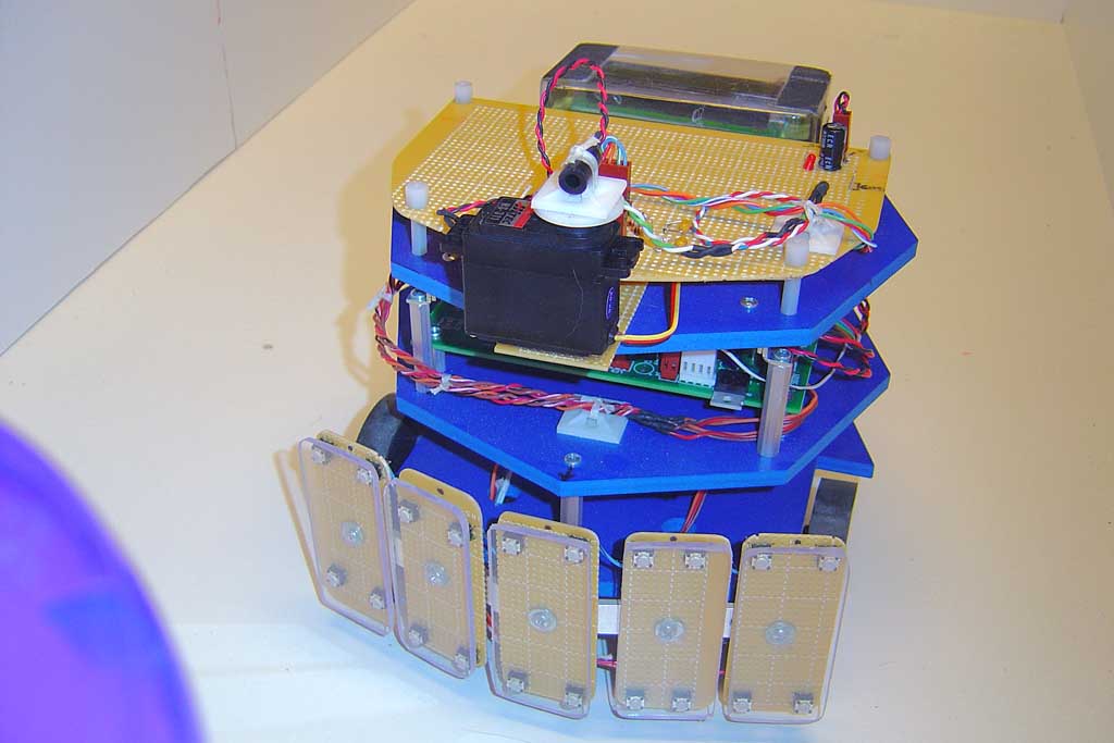
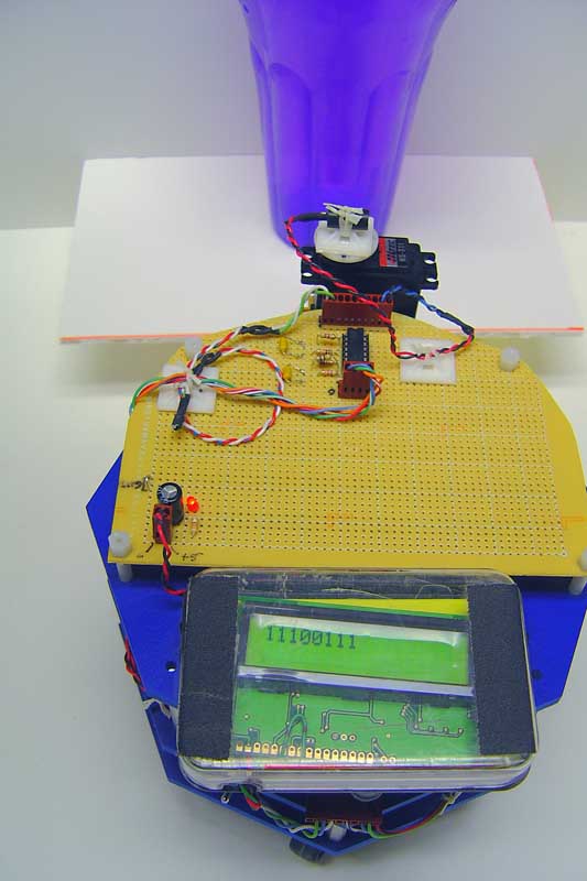
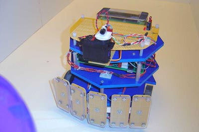
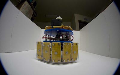
This
new version of the Vision Logic Robot shows the servo motorized
scanning platform on the front top of the main deck. Even though
the slow scanning process makes for processor sharing headaches,
I found that the flexibility of being able to change the pixel
resolution with a simple code change was enticing enough to demonstrate
the concept. For this initial run, we don't move the robot yet,
it is simply scanning the surroundings for brightness variations
and producing an interpretation on the LCD display. The scanning
angle is 180 degrees from left to right and takes about half
a second each direction. |
 Click above Thumbnail for a larger view
|
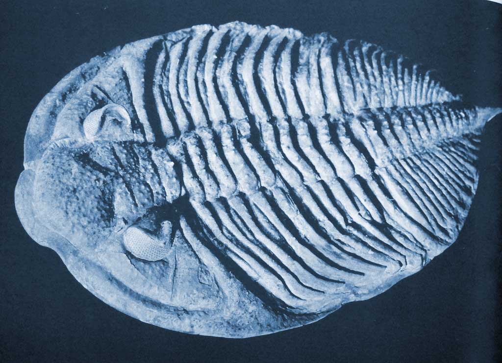
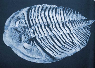
This
is a full body view of an ancient 400 million year old trilobite
fossil. The eyes are on the left side, and are seen as two arcs
that form a backing for the eye facets. The angle of vision is
astounding, a full 360 degrees of visual range is seen here -
however you must remember this is in a very narrow plane that
essentially looks straight forward, and a backwards over the
back of the animal. It cannot see down, up or upward at any angle.
Despite this limitation, trilobites were amongst the most successful
animals ever on earth and lasted hundreds of millions of years
before going extinct. |
 Click above Thumbnail
for a larger view
Click above Thumbnail
for a larger view
|
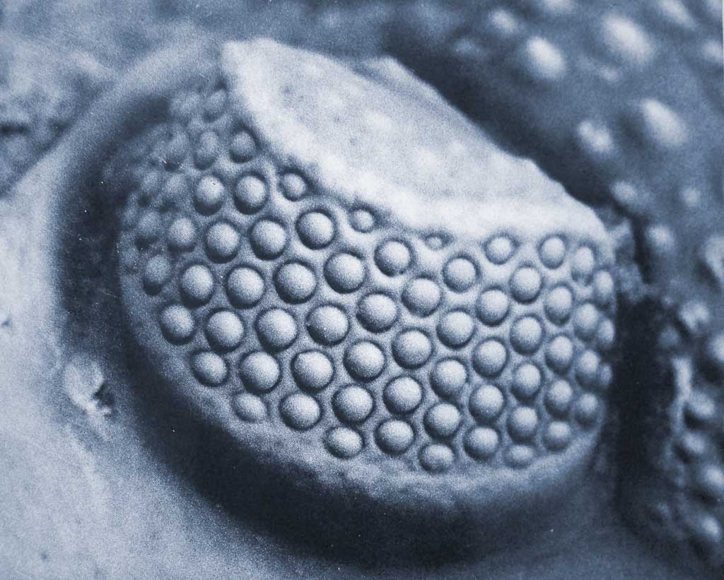
A
close up of a trilobite eye which shows the individual eye lenses.
Each lens focuses light onto a small patch of retinal photo sensors,
but no image is formed. Each eye acts a single very sensitive
photocell, and the resolution is very crude on the surroundings
of the animal. Later in the evolution of the trilobites, the
resolution increased 10 times or more and less crude images were
impressed on to the primitive brain of the animal. The animals
amazing success is no doubt due in part to the invention of a
mosaic type vision of the animals surroundings. |
 Click above Thumbnail for
a larger view
Click above Thumbnail for
 a larger view
|
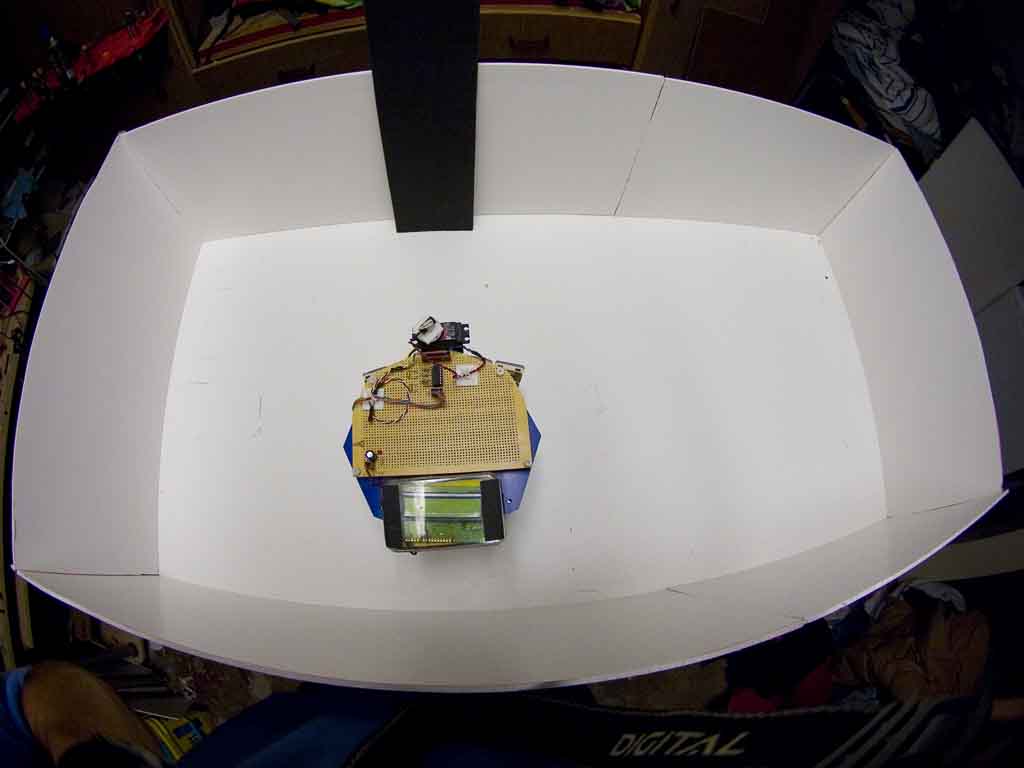
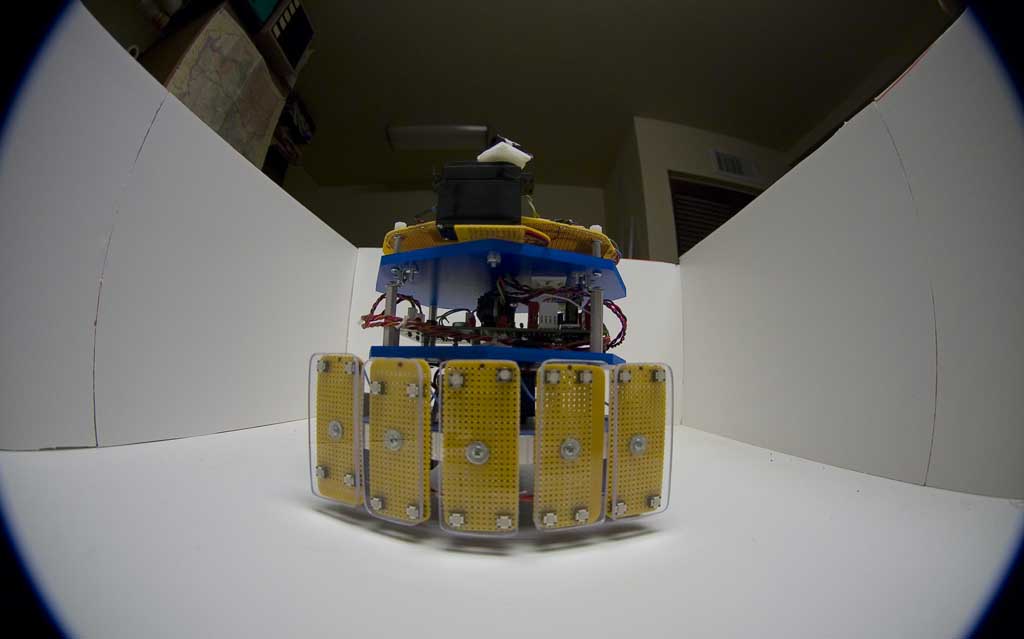
The
Vision Logic Robot (VLR) in the test arena. The walls out of
white foam board have been extended upward to give the vision
system under test a controlled plain background for basic vision
performance characterization to be made. Objects such as this
black piece of foam board can be placed into the arena, and the
robots response noted. |
 Click above Thumbnail for a larger view
|
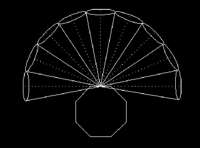
The
motorized vision scanner produces 9 pixel resolution, each non
overlapping field is 22.5 degrees wide and encompasses a range
of 180 degrees of field. The scan starts on the left and moves
right, at 22.5 degree increments stopping only for a few tens
of milliseconds at each position to take an analog reading from
the photo transistor. This is buffered with a rail to rail Op
amp, and sent to the analog input of the processor. |
 Click above Thumbnail
for a larger view
Click above Thumbnail
 for a larger view
|
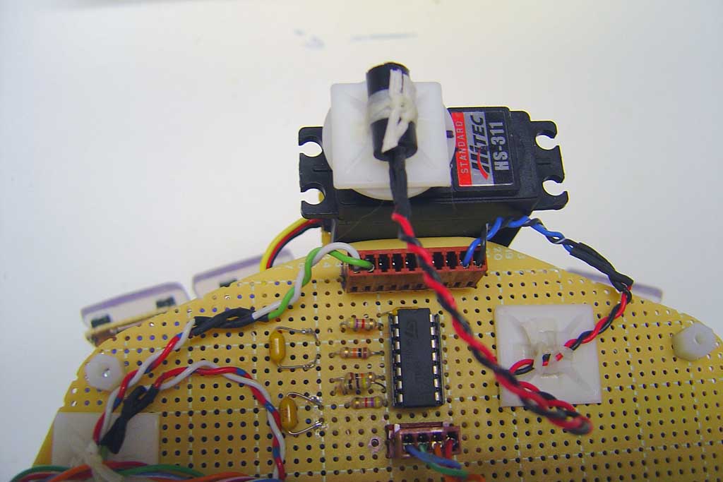
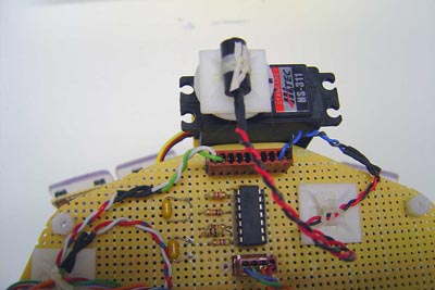
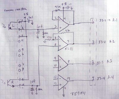
Implementation
of the scanner was fairly straightforward, a standard hobby servo
motor had the photocell assembly secured on top and could be
slewed quickly to the next position. The photocell amplifiers
are on the circuit board and consist of a very nice rail to rail
single supply op amp, the quad package TS954 from Texas Instruments. |
Movie 1
|
A
short mpg movie of the scanner in action showing the right-left
then left-right scan. |
 Click above Thumbnail
for a larger view
Click above Thumbnail
for a larger view
|
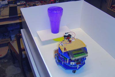
In
an experiment, the robot is manually placed various distances
and angles from the target, seen here as a medium colored cup. |
 Click above Thumbnail for a larger view
|
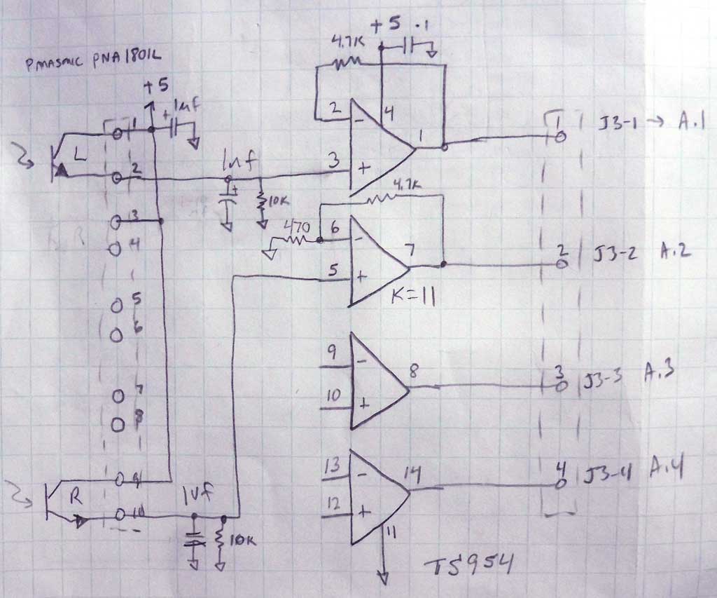
Schematic
of the photocell amplifier. I'm only using one photo detector
for this experiment. The RC filter keeps out the 120hz ripple
from the overhead fluorescent lamp from slamming the amplifiers. |
 Click above Thumbnail for a larger view
|
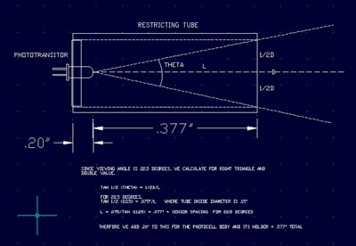
Restrictor
tube calculations. To limit the field of view of the photodetector
to the required 22.5 degrees or any other for that matter, you
use simple trigonometry to calculate the length of the black
restrictor tube. |
 Click above Thumbnail
for a larger view
Click above Thumbnail
 for a larger view
|
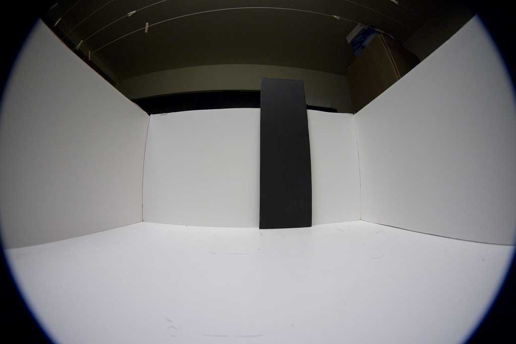
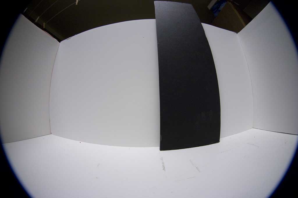
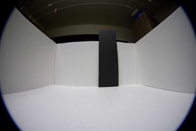
A
180 degree fish eye lens view of what the robot will see at 2
feet from the 5 inch wide target. Notice how small it appears
in the field even that close. This is what the robot will see
as well. |
 Click above Thumbnail
for a larger view
Click above Thumbnail
for a larger view
|
From
the target looking back at the robot in the arena. The scanner
is ready for testing. |
 Click above Thumbnail
for a larger view
Click above Thumbnail
 for a larger view
|
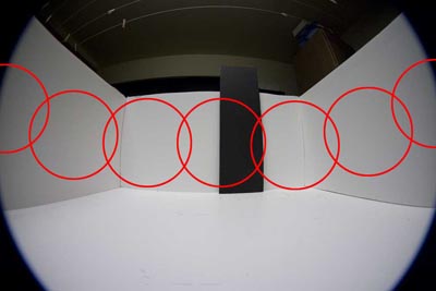
When
the robot scans the field in its one dimensional view narrow
horizontally like our primitive trilobite, its 22.5 degree fields
are super imposed as seen here on the distant target. This target
could be in the real world a cave, tree trunk or anything dark
that might provide information to the animal, or in this case
the robot. |
 Click above Thumbnail
for a larger view
Click above Thumbnail
for a larger view
|
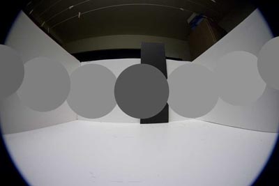
As
the photocell reads each circle it puts out an average of the
brightness in each field integrated over the entire 22.5 degree
circle. Note that at this very poor resolution, the totally black
target gets averaged in with its white surroundings, and comes
out as a medium gray. This is what the robot will have to interpret
as its visual scene. |

|
The
above image scan produces a 9 pixel image of a strip extending
180 degrees around the front of the robot. See how the black
target is hardly visible compared to the shadings on the walls
of the enclosure. At this resolution, the robot would not be
able to find the target since it looks just like the walls shadings. |
 Click above Thumbnail
for a larger view
Click above Thumbnail
for a larger view
|
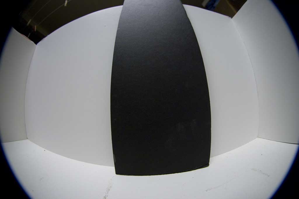
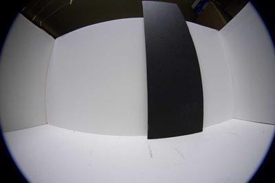
Moving
six inches away from the target makes it take up much more of
the scene. Again, this is what the robot has to see - a full
180 degree field from its left side on the left to its right
side on the right. (Aren't fish eye lenses fun!) |
 |
Now
we can see the dark target! Again, as the circular fields cover
the edges of the target, we get a medium gray shade on each side
of the black target. Think of this as a rather blurry view of
the world. |

|
In
this case the above data was converted to a 1 or 0 binary value
pattern for analysis. Remember, robots see the world as 1's and
0's and have to convert this greyscale data to binary to view. |
|
There
are many more sophisticated methods to analyze the gray scale
values in an image as well, but I'm going to keep it simple right
now and see what can be done on the crudest levels. To create
this binary view, the data is scanned by the robots processor
and a maximum and minimum value is extracted. A threshold slice
point is calculated from this range, and used to covert the greyscale
image into a usable data format for processing. the formulas
for this conversion are:
threshold = (Max
- Min)/3 + Min
This gives a very
solid binary representation of the image.
|
 Click above Thumbnail
for a larger view
Click above Thumbnail
for a larger view
|
At
a distance of a few inches, the target becomes quite dominant.
This is how close I had to have the purple cup to see it at all.
The contrast is key here. The bottom line is - Low resolution
vision means short detection range. This is why there was a push
in evolution for increasingly higher visual acuity and more pixels! |

|
Greyscale
data for above scan |

|
Thresholded
data for the processor. A very strong detection indeed. |
 Click above Thumbnail
for a larger view
Click above Thumbnail
for a larger view
|
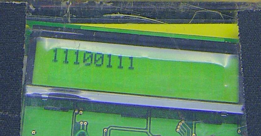
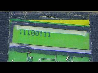
Live
display image from a test run, the above image was represented
as 0 for below threshold, and 1 for above. For the nine positions
measured, you can see the walls read 1's, and the black target
reads 0's. With this visual data available, the robot could for
instance determine the distance and position of a known obstacle
and the direction it had to go to avoid it. |
 Click above Thumbnail
for a larger view
Click above Thumbnail
for a larger view
|
For the purple
cup, point blank or up to maybe six inches was the detection
limit (look at the display in the enlarged image), since the
contrast was much lower. The real world is obviously not all
black and white, and when we get higher visual resolution in
future projects, we can see the purple cup further away. For
now, the robotics applications can be understood clearly. Black
and white targets can be placed in the home environment and used
as beacons to guide the robot to its destination. It can also
mark with a unique pattern directions to go and a rough range
can be calculated based on object contrast.
In our next step,
the robot will be moving, and talking. I will demonstrate visual
navigation basics with such crude vision, and object avoidance
and identification. The final point here is that compared to
a blind bumper endowed home robot, a new level of environmental
awareness can be made available to the device, and is entirely
passive - no laser beams or IR transmitters required!
|
|