|
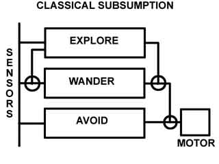
Here is a primer on how to design and apply this remarkable microcontroller architecture design to your next robotics project. My goal here is to show you the basic concepts, a step by step development process, and ultimately take you through a real application and build a small robot that is completely controlled by this architecture. Since this is a very abstract and complex subject, my goals are to describe the process in simplified everyday terms so you can apply this to your application with a minimal learning curve. Note: Thanks to members of the Seattle Robotics Club for pointing out how Brooks method of subsumption has been superceeded by a different method of Subsumption in modern times. While Brooks based his architecture on the lower levels having the lowest competence with overlying levels of increasing competence and decreasing priority. Modern Subsumption arranges the layers from bottom to top in increasing PRIORITIES, that can subsume lower levels of less priority. Still, the history of Subsumption Architecture stands firmly on the foundations laid down by Rodney Brooks in 1985. Background - What is Subsumption Architecture? In September, 1985 Rodney Brooks of the MIT Mobile Robotics published a landmark paper on a new architecture for constructing and programming robot controllers. (Brains) This concept allows parallel processors to be divided up into Levels of behavior in which the upper levels which perform higher cognitive functions can subsume lower levels and take over control. In plain terms, you have a stack of 2 to 8 layers of processors, the top layers can override (subsume) any commands the lower layers give to for example to the motors, or other output devices so they can perform more advanced behaviors.
Layers of Control Advantages - The robot control system can be constructed in functioning groups, each level is a complete working system with a fully competent behavior for survival of the robot. - Each element of every level is a simplified collection of completely asynchronous Finite State Machines (more on that later) - Parallel processing of low bandwidth elements can achieve far better performance and realism of achieving an insect like intelligence, and is far easier to program than one huge linear program. - The simple Muliti-Processor architecture can do as many simultaneous tasks or behaviors simultaneously, using inexpensive "dime a dozen" processors.
Disadvantages - This is a much more hardware oriented design approach. If you are not comfortable with working with half a dozen microprocessors at the same time, or building a larger board to accommodate a few more elements, than this may not be a viable solution. I've built this architecture before, and used $1.50 PIC processors such as the PIC12F629 or the $2 PIC16F628 with no problems. - Your brain will spin sometimes trying to think in the abstract subsumptive behavior mode! The Eight Layers System Brooks proposed a seven layers of behavior system, which he was able to achieve in the labs at MIT to about the third level in his experiments, starting with Level 0: Level 0: Avoid - Avoid contacts with objects, both moving and stationary Level 1: Wander - Wander aimlessly around without hitting things Level 2: Explore - Identify the most distant reachable goal and go to them. Level 3: Mapping - Build maps of the environment and plan routes from one place to another. Level 4: Changes - Notice changes in the environment Level 5: Reason - Reason about the world and perform tasks related to certain objects Level 6: Formulate - Change the local environment in some way. Level 7: Reason 2 - Reason on the behavior of objects in the environment and modify plans accordingly. Obviously, this gets pretty off the wall near the end of this list, but the idea is to have higher layers of behavior - hence artificial intelligence (A.I.) gradually subsume control of the robot. I can see getting into about layer 4 or 5 in home robotics.
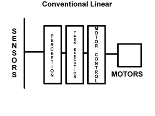
Behaviors are Everything Perhaps the biggest change you will have to make in using this architecture is the way YOU think! Normally, programming bots consists of loops, subroutines and generally continues looping over and over again to keep the robot running. Most robots built by home builders are reactive machines built this way. They simply go forward, until they hit something, then veer away from it traveling until they either get stuck or run out of batteries. From what I've seen, nearly 95 percent of home bots are made this way. How much more work would it be to say thrown in a socket, and a few bucks more in processors and have the next level of AI at your disposal? Now, onto designing an actual working Subsumption robot... Asynchronous Augumented Finite State Machines What is a AFSM?
Testing the States As with any multi IC project, each and every module in the set will have to be thoroughly debugged and tested before inclusion in each level. Programs for each element or module as Brooks calls them are usually quite simple, and it is only together the complex actions result. We certainly don't want an erratic crazed module subsuming a normally quiet and sane robot! Physical Construction Considerations Board size and layout Consider using a protoboard that is twice to four times the surface area of a conventional project. Multi processors can take up a lot of real estate, with each level using anywhere between 1 and half a dozen small micros. But just keep in mind how much simpler the programming will be in the end. lo Component Selection I can't imagine building this with the huge Basic Stamps, with their hefty $50 price tag each and voluptuous mini PCB's, however, one can easily achieve a few levels of Subsumption with only two Basic Stamps, and at a bearable cost. The best solution is to use the dirt cheap PIC processors by Microchip. I program them with PICbasic by Microengineering Labs and can easily get them for under a dollar each for the more basic ones, or a whopping 5 bucks for the really meaty fast ones. For under $20 in processors, which don't need the crystal - use the internal RC oscillator - you can make a really capable architecture in your new system. Wiring Considerations The two routes for working with the relatively simple wiring of these devices are conventional proto boards from Radio Shack, with sockets for ALL ICs, and using small 30 gauge solid wire wrap wire to interconnect. Alternately, you can certainly prototype it up on a solderless breadboard (also from RS), and as an additional and more final option, you can for under $20 get circuit boards made by Express PCB.com for some really professional results. Programming Considerations Changing your thinking You've got to stop thinking in terms of giant endless program loops and one giant complicated program for starters. Were going to be working with small blocks of programs, each an individual finite state machine with simple standard programming each. Lets start by roughing out a basic Subsumption demonstration, using two levels, and only a few components. From this you'll be able to grow and create you own more advanced systems. Designing for Subsumption There are many ways to implement a subsumptive architecture. One way is a giant multitasking processor, with hordes of subroutines each representing a FSM. Each sub routine is looped through in a single pass, and the results and place holder are stored in RAM. Then we jump to the next FSM subroutine. After running a dozen or more of these at a high rate of speed, we start over again on each one, taking off from our saved positions in RAM from last time. This is multitasking "almost" parallel architecture. If your a computer genius which I am not, you may go that route to implement SA. Here's how I did it, from a much simpler hardware aspect.
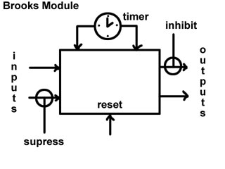
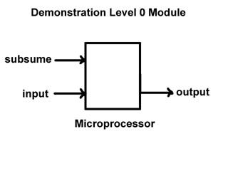
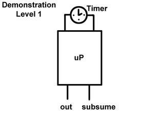
The fun begins when we connect the two blocks together. The output of the Level 1 module connects to the input of the Level 0 module. Also the Subsume output connects to the Subsume input of the Level 0. What will happen? Level 0 is running happily along, blinking its LED on its output every second. Then, for no apparent reason, the Level 1 module subsumes the lower one and now the LED on the output of the Level 0 module blinks at 10 Hz! Then after 10 seconds, it goes back to its normal mindless state and blinks happily at 1 Hz. Considering the Ramifications This simple experiment which cost me $2 in parts is a very simplified demonstration on how the Subsumption Architecture works. Upper layers taking control of lower layers, asynchronously. If I would have had a third layer - Level 2, it could have say slammed out something more intelligent, such as Morse code of the outside temperature or similar. It just grows and grows. Creating a simplified robotic demonstration
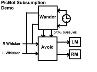
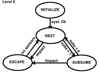
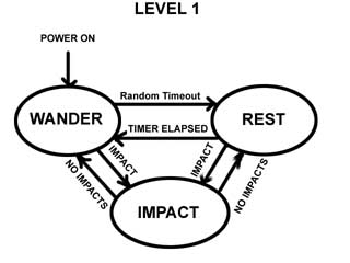
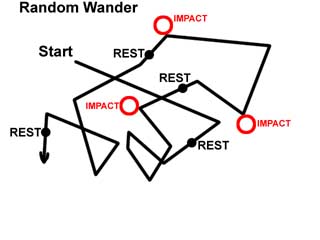
How it works Keeping in lines with Brooks Hierarchy, Level 0, the Avoid module behaves in the following manner: - Responds to whisker contact by rotating the other way. - Touching both whiskers at once yields a backing off behavior. - No forward movement when not being disturbed. We do not have the "brains" at this lowest of levels to roam yet. What we have is a core set of reflexes, like the inner brain in our bodies that respond instinctively to external stimuli. You can poke it and it will turn away. You can chase it by grabbing both whiskers and it will continue to run away backwards until you stop. The Level 1 Module which subsumes Level 0 is also running its little program. Using its on board timer, it subsumes the Avoid module every 10 seconds and generates random headings for it to follow. Then it leaves it alone for another 10 seconds, and lets it run its program. Now here's the great part - while subsumed, and its wandering about if you hit something and activate the whisker sensors it will use the Level 0 functions and turn away or back up from the impact. In other words you are running in subsumed mode unless you hit then the subsume line on the Wander module goes back to low temporarily and when the impact is cleared, you return to normal subsumed operation. This happens because the Wander module has the same inputs as everyone else, in this case when it sees a whisker impact, it stops subsuming until the event is over with. Its crucial to understand that the upper leaves use the lower levels as part of their behavior. Because I don't have to program the higher levels with lower level responses, this GREATLY simplifies the programming.
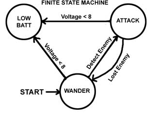
Integrating the AFSM into the Architecture Now to make all this work, lets discuss what is actually going on INSIDE each processor. Level 0 Finite State Machine
Level 1 Finite State Machine
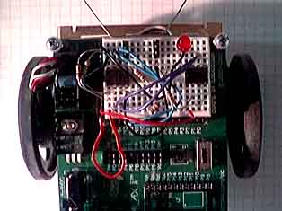
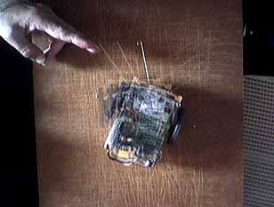
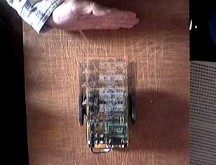
Connecting it all together With the appropriate connections made, the power was turned on, and we can see Subsumption in action. Here are some photos and diagrams to illustrate the behavior of such an simple architecture. Testing with PIC-Bot
Final Thoughts Processor selection for modules This simple demonstration used some very inexpensive processors, with only six (yes six) I/O's but resulted in some very complex movements of PIC-Bot. For the next version of a Subsumptive Architecture robot, it would be better to use the $1.80 16F628 processor because of its 16 I/O lines will allow a wider degree of sensory inputs and allow a full 4 bits or more of Subsumption to both inputs and outputs. A key element also here on the PICs is that for this application, most of the processors can be run in the RC time base mode, so no external parts are needed. Taking it from here We are currently finishing up our Ostracode project which uses a single processor and only a few timed subroutines for some overriding control. Our next robot in which we are in the parts buying stage at this time will incorporate full Subsumption architecture, and four levels of Subsumption. Stay tuned! Chris Schur |