|
|
|
|
|
|

Introduction
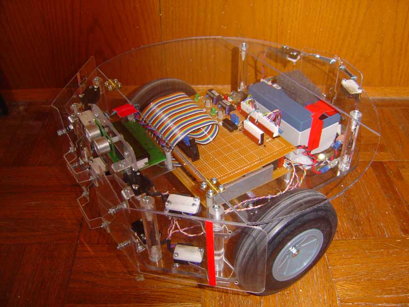
Here is the first IR beacon test for our robot. The beacon will be used to navigate to the battery charger and for a point to drop off items collected later on. It will be located in a well traveled area of our house, which the robot frequents often. Here I will describe the basic operation, some tips on making a beacon station, and some movies of the actual docking tests (no charger yet!). Now we are one step away from a perpetual machine.
Theory of Operation
The beacon sensor was discussed at some length in this previous article. It has now been mounted in the center front of the robot, and aiming straight forward. Here we will now discuss the operation of the beacon itself. The beacon must generate a precision 38 - 40 KHz signal to be picked up by the beacon sensor. One way is to use a simple oscillator, using RC values to set the frequency. BAD IDEA. The temperature drift for one will make the beacon unpredictable, and your robot could suffer a slow fading death. A crystal oscillator will ensure accuracy, low cost and will not drift appreciably over time and a wide range of temperatures. You can either use a high frequency oscillator and divide the rate down to 38.5Kc or do it the way we did it, with an 89 cent microcontroller.
Our method was to use a 10.000 MHz crystal on our PIC 12F629 processor, and simply have the output line go high for 13 micro seconds, and then low for the same time. This is repeated over and over and generates a 39KHz signal to drive the IR LED beacon. It only takes a few program steps - but you may have to make it slightly shorter in time, to take into account the command execution time, which for us made the time 11 micro seconds instead. Using a processor like this has an additional advantage - later on we can modulate the waveform into bursts that can be counted at the receive end later for beacon identification. More on this method here.
The PIC processor drives an NPN transistor which switches ground on and off via collector load to the five LEDs. A series power adjustment pot sets the output level if desired. One of the LEDs is red. That lets us know the beacon is on.
Construction
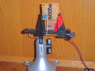
The beacon will be later housed in a cylinder, at the proper height above the charger contacts. For now, we mounted the board in a board vice, with the micro controller board on the back, with a 5v regulator. The whole affair is run for now off a single 9v battery. Eventually, it will run off the battery charger output.
Testing
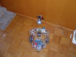
The robot was allowed to drive freely around the living room at first, to confirm operation. side range is about 4 feet at this time, and head on range close to 8. When we first tested it, we simply made the robot beep when it saw the charger. That gave us the confidence on its range and function. Next the robot was instructed to drive toward the active sensor. If both sensors were active, it was to go forward. For No active sensors the Charge module was not to subsume, and the normal cruise module took over. Thats the beauty of subsumption architecture - stacked priorities. Charge subsumes the IR Avoid module, so that it can closely approach the charger without being ejected by an escape maneuver. In other words, you must suppress the reaction that the robot normally has when the proximity detectors indicate it is about to hit something. You WANT to hit the charger. BUT - the Bumper Impact module subsumes the Charge Module, so when it does hit something either on the way to the charger or the charger itself in this case, it will do an escape maneuver. The result is once the robot hits the charger post, it bounces back, then goes back at it again and again. Later, this will of course not occur since it will be programed to stop when the battery charger makes contact before it hits the post.
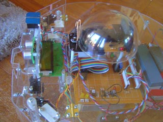
Our temporary charging beacon. It stands 7.5 inches tall. Four high power IR LEDs are wrapped with half inch long heat shrink tubing to limit the output angle to basically straight ahead to limit the intercept angle of the robot so making contact with the charging plates is constrained. The NPN driving transistor is to their left. Approaching the beacon, the error at this point is less than 2 inches accuracy, and will improve with a few small changes to the beacon sensor, primarily to filter the forward looking with a neutral density filter so its not so bright head on. The sides will be left unfiltered so tangential detection is at a maximum. Close up of the Beacon dome on the top center of the robot.Note the guitar strings bumper in front of the dome (left) to keep nasty impacts occurring to the delicate beacon sensor array. (By the way, ALL of the wiring you see here is UNDER the lexan covers ! Movie 1 (300kb) This smallish MPG movie, with sound shows the robot heading right toward the beacon, and at the last minute, I pull the battery on the beacon, shutting it down. The subsumption architecture turns off the Charge module from subsuming, and its goes back to normal operation, looking for the charger elsewhere. Movie 2 (564kb) Ok, this MPG movie has some great sound effects. A very significant event here for us, one of the first docking tests. The bot is set to move along the path in the living room tangentially from the beacon, it is hungry and looking for a beacon. When it encounters the beacon signal it stops, lets out a "happy" sound it has found "food", and rotates toward it, drives right to it. Now since I haven't installed the docking sensor yet which will be part of the charger part, its bouncing off when the impact module subsumes, over and over. Pretty cool, ay? Movie 3 (630kb) Another really demonstrative video, the robot heads toward the beacon, and starts bouncing off. I then disconnect the battery on the beacon and INSTANTLY the bot turns away and moves on, still looking for the charger. Movie 4 (7.9Mb) This is the BIG one. For high bandwidth users. its a 640x480 shot of the docking in progress - as it bangs up the charger trying to find its food. Later on, contacts on the bottom of the robot will detect the electrical connection BEFORE it hits the post and stop it instantly, shut down the entire system to a low current mode ( about 17 ma) and feed. The robot normally draws 400ma or so. Notice how the cat percieves the robot - a curiosity, but a normal thing around our house!