 |
|
 |

In this chapter, we will cover how to effectively select a charger beacon system to fit your needs, and a wide range of methods which can be used to guide your robot safely to its battery charger. We will try to show to you that the best overall techniques which can be accomplished for a minimum of expense involve the use of invisible infrared (IR) light, which is both reliable and can be used for additional navigation functions as well.
An Overview of Beacon Systems
Analog vs Digital
You have essentially two choices when defining the charger beacon - an analog approach, or to go all digital. The path you take may be dictated by your level of experience in in working with each technology, or by the nature of the robots environment. An example of an analog approach would be to measure the voltage levels produced by a series of sensors on the robot produced by a constant brightness light source at the charger. Here, you would direct the robot to home in on the charger by comparing the voltages in the analog sense, with op amps and analog inputs interfacing to your micro controllers.
An example of a digital type beacon system would be for a bi-level light or sonic source on the charger with possibly encoded binary data in the beam to be received by a digital sensory array on the robot carefully designed to allow the precise location of the beacon source or orientation to be determined. Such signals can be multiplexed or directly sent into the digital TTL level inputs of the micro controllers.
Internal Processing Circuitry
In the case of charging beacons, the simplest approach is not usually the best approach for the given application. In the analog world for example, one could put a bare light bulb over the top of the charger contacts and by using cadmium sulfide photocells, use analog fuzzy logic to steer to the charger base. However in a brightly lit room with a window or two, such a solution would simply not work. The stray light from the windows would confuse the robot, and it may go for the window instead of the charger, dooming the robot to never reach its charger. In this case, a clear cut approach is one that puts out a significantly different - a unique signal that is not possible for the robot to confuse it with anything else in the room. A sonic beacon for example that produces a crisp high frequency chirp can be a unique feature in the room, as can a specific color such as orange that will not appear anywhere else in the robots range of vision can be detected with a small CMOS camera mounted on the robot. So the robot designer must choose a unique beacon identification that the robot will be able to find easily, and one that is both cost effective and within the technical abilities of the roboticists.
Cost
For commercial and academic applications, cost is usually not the issue when selecting the type of beacon to be used in a system. The selection is usually based on the academic curriculum, lab financial budget constraints, or to fit the needs of a large warehouse environment or factory. For the rest of us, constructing a beacon to guide the robot safely to the charger contacts can be both a successful and inexpensive venture, easily serving the needs of a smaller and more restricted home environment. We will be discussing both types of systems to be complete, and it will be the choice of the robotics engineer or home robot experimenter to select the options that best suits their situation.
Range
For commercial and academic laboratory environments, a longer range is usually mandatory, and often multiple beacons must be carefully placed at selected nodes in specific locations to be effective. An example would be a small low powered sweeping laser beacon that can traverse thousands of feet to guide the robot. In a home environment or small office the choices for a short to moderate range beacon are dramatically increased and much lower in costs. When selecting the type of beacon to be used, the designer must consider the typical range under all environmental conditions such as bright lighting, noisy environments, or obstructions that the robot may encounter on its way to the charging base. For a typical home environment, a range of four to eight feet is usually sufficient.
Power Consumption
A primary consideration in beacon and sensor selection is the power consumption of the sensor that will be on the robot itself. While the beacon on the charger typically is powered by a DC power supply that is plugged into the AC line on the wall, the robot must provide all the power to both move itself about, complete its task and also detect and dock with the charger beacon. A sensory array that draws 500 milliamps would not work for a home robot for example, the batteries would be better utilized by a much more thrifty detection system. With an industrial application such as a warehouse floor buffer, or pallet delivery robot, the batteries can be much larger and support a much more sophisticated detection array such as a larger CCD or CMOS camera array which can draw several amps. Again, the roboticist must allow in his power budget as it is called for the sensor array that will be used intermittently for charger homing without putting a strain on the allowance for the other critical robot systems.
A Sampling of Beacon types
In this section, I will try to give an overview of some of the types of charger beacon systems that have been used to some success in todays robots. You as the robotics systems engineer must look over your options, and select the beacon setup that will best suit the robots application. This list is not exhaustive, but may stimulate your mind into devising something new, and exciting to share with the robotics community. I've also thrown in some pretty wild ideas at the end that may be pretty outrageous concepts, but will certainly either get you thinking, or amuse you at my sense of humor.
Infrared Systems
Single Beam Configuration
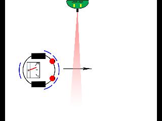
This is the most common generic docking beacon configuration used today. Consisting of a single narrow IR beam, the robot merely has to cross the path of the beam, and the proximity detector will alert the robot that the beacon is nearby. The best location for such a system is in a hall way or narrow passage in which the robot frequents often, such that the beams detection range will reach all the way to the opposite wall. Then no matter where the robot crosses by in the hallway, it will detect the beacons proximity. This configuration is inexpensive, and often multiple chargers are placed in a larger work area to make it easier on their robot to find.
Here we illustrate that a robot with a centrally mounted IR proximity detector will almost always detect the IR beam when crossing a somewhat confined corridor or hallway. This simple approach can work very well if the beam is confined to a fairly narrow cone, such as less than 10 degrees to keep the robot tracking all the way to the charger on the way in to the base.
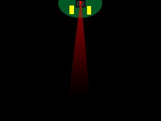
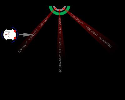
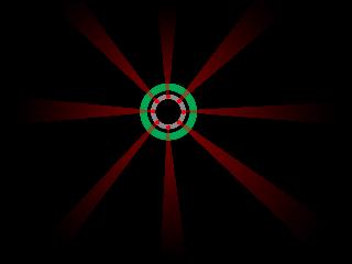
Omni Directional multi - Beam
In this configuration, a ring shaped pedestal in located centrally in the robots work area. Emanating from the central cylindrical shaped charging port are multiple IR beams converging a wide range such that the beacon can be seen anywhere in the room if the robot is within reception range. Each IR beam has its own set of electrical contacts underneath it, and the robot can dock with any of the many beams to provide great flexibility and coverage in the robots work area. The disadvantage of such an arrangement is that if the beacon is to be in a corner of the room, this configuration will not work, since the beams that are against the wall will project false targets on to the rear wall surface which will confuse the robot.
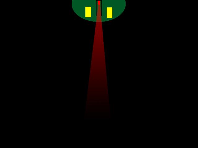
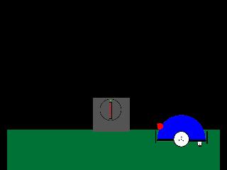
Tube confined Beacon
Just to illustrate how you can modify the LED output angle for an IR beacon. By putting the lamp in the bottom of a tube such as 1/4 inch heat shrink tubing or other flat black tube, we can shape the beam to become narrow as we need to allow the robot to track right into the contacts. Too wide of a beam will allow the robot to drive in crooked and may not connect.
The Roomba docking technique
This is roughly what IRobot does with its robo-vac to get it to the charger. An Omni directional receiver in the front of the robot mounted inside a stubby turret contains an Omni cone receiver (covered next chapter) which detects the IR beam and its embedded binary code. The code tells the robot which beam it has encountered and can be used to guide it in. Crude, but usable and puts the complexity in the beacon rather than the robot. This scenario has issues however. Users on the "Roomba Review" forum report all sorts of interesting dances the robot gets into when it cannot home in one the central beam. The dreaded "Circle Dance" is well known.
Modulated IR Light Bar
We used this approach in our PAAMI robot successfully. The line of IR LED's form a brilliant source that can be seen from across the room or office and by putting them in a line in a vertical manner, you still retain an excellent sharp point source to home in on with a differential vane type detector (covered next chapter). It is inexpensive, long range, and allows the use of binary data to be encoded on the beam for identification.
Optical Light Based Systems
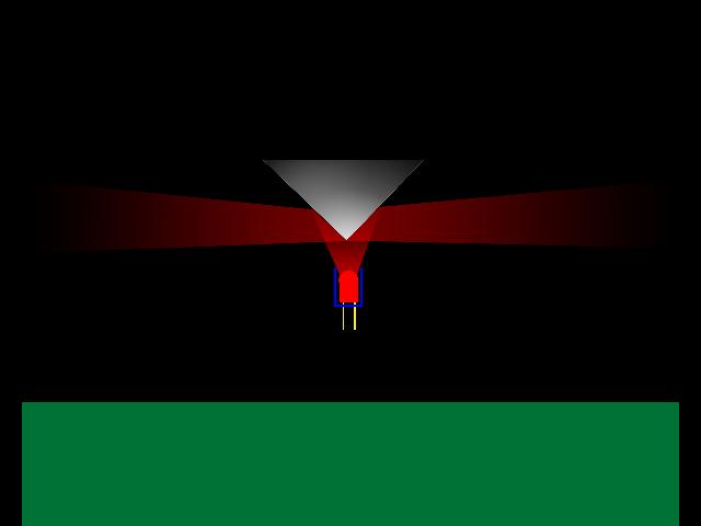
Omni Cone Beacon
This actually can work fairly well but the range is less than most direct beam designs. Imagine a single bright IR LED pointing straight up at a mirrored cone. The result if the angle of the cone is carefully chosen is to send a bright ring of light in all directions evenly, and as viewed from a robot, the cone will reflect a nice image of the LED right at the robot from any angle. The cone cannot be randomly made. I will detail later on how to do the cone mathematics should you choose to try this route. Not for the faint of mathematical heart!
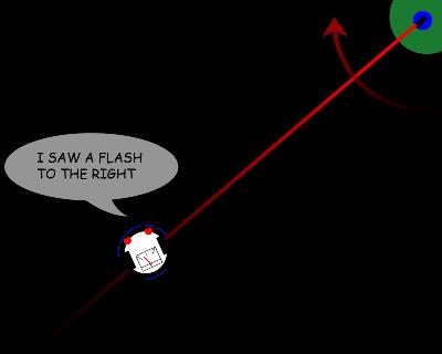
Laser Beacon Scanner
An inexpensive laser pointer can be usually be modified by modulating its power supply with about 30 to 120 Hz and serve as a unique beacon source. The beam sweeps across the entire room using a servo motor, and can be seen for hundreds of feet. What the robot sees however is not a constant light calling it softly from a distant corner, but a flash that is very brief and during that period it must measure its modulation frequency and determine its exact direction. While this is not an insurmountable optical and programming challenge, it is for more advanced robotics engineers for sure. But its great range and flexibility allow for use in triangulation as well, when multiple beacons are used.
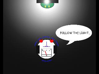
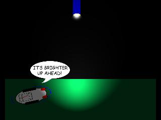
Bright Light Source
You will find this technique listed in many of the older books and publications. It is a classic experiment for your robot to home in on a candle, small light bulb or flashlight. Why not use it for finding the battery charger? If the work area is dark such as at night, this works fairly well, one must be cautious for specular glints to misguide the robot astray. But in the daytime, this non modulated lamp is not easy to see in a well lit room! Normally, a pair of CdS photocells are used to home in with a single vane type sensor array.
Sumo Ring Homing
Based on some of the Sumo completions, the robot can using only two sensors pointed straight up determine where the center of the beam of light is at its brightest. The robot can then drive over the charger contacts and connect. Obviously cannot be used in brightly lit rooms, but both photo transistors and CdS cells work well here.
Sonic Systems
UV Light Source
Even in a moderately lit office or room, a small tube type UV long wave lamp fixture will provide a dandy unique light source to identify and dock with. Being a long tall tube, it acts like the previously mentioned LED line array, and makes accurate docking a snap. I might also mention that bugs love this color light as well...
Optical/Imaging Systems
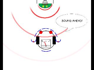
Point Audio Source
This technique was inspired by a study in which the male cricket homes in on the female which is chirping at some distance. The robot will be able to detect the differential amplitude or phase of the sound source, which is typically a one or two tone mix. While this may work fine in a quiet home environment, a loud factory floor may not be suitable. Also, if the sound tones are in the human audible range, the peeping sound may become an irritant very quickly!
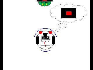
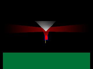
Color Target and Camera
This method is similar to some of the ball chasing antics of some robots that are equipped with a CMU cam designed by Carnegie Mellon University. The goal is to scan the room for a specific color or color patterns such as red surrounded by black as in this example. The robot then drives directly to the pattern lining up the shape as it goes in. An additional color spot can be placed in between blinders just over the charging contacts for a refined tracking when the robot is near the beacon. This is of course expensive and sophisticated both in electronics and programming. But in areas of constant lighting, this could be the ultimate beacon!
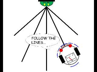
Line following
A very simple approach is to simply put converging lines on the floor and let the robot follow the lines in using 4 floor pointing reflectance sensors on the front bottom of the robot. This simplified approach relies heavily on many years of work in competitions which feature robots following lines to a finish. An interesting facet of this method is that it is about the only one that allows a curving path to the charger, around corners even! Of coarse this is suitable in a work environment, but I'm afraid my wife may not allow me to paint black lines all over the dining room floor...
Top of the Hill Approach
Now here is a technique that you wont see every day. The robot can use tilt sensors to enable it to drive to the top of any incline. Waiting at the top will be the charging station. An example may be for a lawn mower robot. When it finds the ramp, it may elect to back off and continue to mow for a while if the batteries are not low. But when the batteries need a boost, it will climb the ramp and safely connect up. With the robots shadow on the charger at the top, you may be able to use IR LEDs to line it up exactly.
Wind Beacon
Ok, this one is a bit off the wall, but imagine a small fan in one corner blowing outward into the room. when the robots anemometer detects a wind (prox detector) the vane type direction sensor can be used to guide it in. I didn't try this one, but you could be the first!
Working with Infrared Beacons
Simplified Detection
Of all the basic systems for beacons we have discussed so far, the most functional and cost effective systems rely on modulated infrared light, or IR for short. Here, with a variety of configurations we can have a selection of ranges, beam configurations and use a wide variety of homing techniques. The beacon can be as simple as a single beam of light, reaching across a hall way to an adjacent wall which the robot will traverse frequently in its travels. Or it can be a set of multiple beams coming from a central source allowing access from a large number of approach angles over the entire room. It is inexpensive, a simple modulated IR source can be built for under $10 in parts, modulating the beam with any number of frequencies depending on the sensor in the robot. Therefore it is our opinion, and that of many other experienced roboticists that this is the path to follow that will lead to the greatest success in creating a beacon that our robots can easily find their chargers with.
ID and Data Compatibility
One very useful additional feature of modulated IR is that we can also modulate the pulsing beam with a lower frequency (about 10x lower) to include a binary data stream within the beam. This can convey beam identification such as in the "Roomba style" docking stations, positional angles of the charger relative to the robot, or even send data updates on tasks from a central computer. Such flexibility in such a simple system makes it virtually ideal for the home robotics frontier, and has many useful applications in industrial situations as well.
Safety
One note on safety, low power modulated IR is both safe and suitable for homes with pets, in busy office environments, and with children. This added bonus makes it an attractive system for the home and office enviornments. Higher power systems such as scanning laser beams, sonic beacons, and strobes are not suitable for this environment. But can be used effectively in larger industrial and commercial applications where typically the robots work areas are separate from the areas in which the people operate.