GeoBot 1 Digital Compass Design Considerations Updated 5/12/06
Introduction
Of primary concern to any outdoor robots tasks is that the robot know which direction it is currently pointing (Current Bearing) and in which direction it must go to reach its destination, way point or final goal (Bearing). One commonly employed tool to accomplish this feat is the use of a microcontroller accessible digital compass to provided the Current Bearing of the robot in its environment. Here on the Geobot, we employ the Devantech R117 Electronic compass, which works very well in this machines unrestricted open outdoor environment. Here we will detail how we used this device, in Part 1 of this article on the Geobot's directional navigation.
The Hardware
The Devantech Electronic compass which costs well under $100 is a marvel of miniaturization and accuracy. Designed especially for both a serial and PWM output direct into a microcontroller, we found it fairly straightforward to use, but challenging to calibrate for our location here in Arizona. We elected to use the PWM output and measure the pulse width with a dedicated processor, dubbed "the Compass processor". This PIC microcontroller sampled the compass bearing, converted it to degrees and put out the direction to turn to get back to the selected bearing. We will cover this in more detail later.
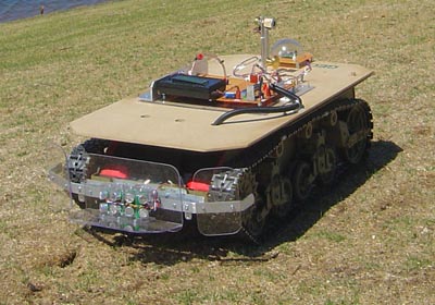
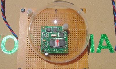
Lets start with a shot of the compass itself, mounted on the back of the Geobot, far away as possible from the electrical and magnetic interference of the two powerful drive motors up front that drive the treads. The 1.5" square PCB is mounted first on a small perf board which holds the pivoting cover dome, and a few external components. Only three wires are needed to operate this device: Ground, +5v and the PWM output line which varies from 1mS to 36.99 mS corresponding to 0 to 359.9 degrees current bearing angle. The compass is sampled at 100mS intervals by measuring the width of the pulse out. This was a bit tricky since my micro would measure a maximum 16bit pulse of only 20mS using the standard 10MHz xtal and Pulsin command.
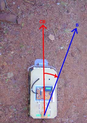
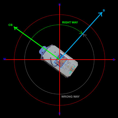
This graphic here demonstrates the basic concept of the two bearing angles we will be working with. First, "B" is the Bearing we wish to go. This number is either derived by calculation and trigonometry or in the case of Geobot's task, it is the first angle it sees as straight ahead when its power is turned on.
"CB" is the current bearing, or where the robot is heading right now. You can see that here, we need to turn to the right about 20 degrees to get back on track to the way we want to be going. These two numbers will be sufficient to point our bot toward a target, and actually get us very near our destination.
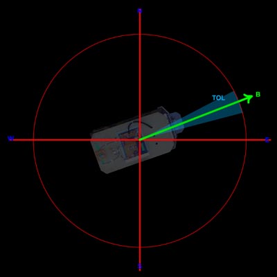
Now lets take a closer look at the two angles, and discuss them in a bit further detail. First, we know that the Bearing angle is of course part of a large circle, that goes from 0 degrees at the top (North) through 90 degrees (East), 180 (South), and 270 (West). We then end up completing our circle at the top again at 359....then 360 which is read as 0 degrees once again.
Along with every Bearing angle, there is a Tolerance. This is the small error angle that is considered "close enough" to the angle we wish to go and for the robot if its within this range to consider it to be right on course. This angle varies depending on the terrain, and the accuracy of the drive train. For our robot, with crude tank tread drive and driving over huge rocks and dips, the angle of +/- 2 degrees was chosen. Any tighter tolerance would not have resulted in a more accurate run.
Next we must consider the math of the correction direction to rotate to get back on coarse. This at first sounds pretty straightforward, but in practice required some careful thinking on our part to get it straight!
The problem is this: If I know my current bearing and the bearing I wish to head, do I turn right or left to make the turn the shortest angular distance possible? We don't want to rotate 359 degrees to the left, when all we had to do is turn 1 degree to the right. Here in this graphic, you can see we are currently going to the upper left at about 300 degrees in direction. To test to the 45 degree Bearing angle and onward to our goal, its a fairly short turn to the right but we must cross the 0 degree point. On the other hand, if we rotate the much longer direction to the left, we simply count down our degrees from 300 to 45 and were done. In our math before we make a decision on which way to turn, we must first calculate the direction and angular amount. The basic formula is:
1. First calculate absolute distance: Diff = ABS(B-CB) If Diff < 180 then Diff = Ds IF Diff > 180 then Ds = 360 - Diff Shortest Distance = Ds B = Final Bearing CB = Current BearingAlso, since our Tolerance is 2degrees, we know we have to move if Diff > 2.
But which direction do we rotate? There are four cases here.
Case 1: IF Diff < 180 and IF B > CB then ROTATE RIGHT
Case 2: IF Diff < 180 and IF B < CB then ROTATE LEFT
Case 3: IF Diff > 180 and IF B > CB then ROTATE LEFT
Case 4: IF Diff > 180 and IF B < CB then ROTATE RIGHT
Finally, we must calculate at this time the direction for the return trip. Lets say we head out at a bearing of 45 degrees, and after a thousand feet want to turn around and return. The calculation is:
If B < 180 then opposite direction = B + 180
If B >= 180 then opposite direction = b - 180.
Now lets go through an example of the above graphic to illustrate the math. Here we have the following conditions:
CB = 300 and B = 45.
Diff = 255 Ds = 360 - 255 = 105 = Shortest distance. Direction to rotate: B < CB so we rotate RIGHT. Finally, the Opposite direction you are heading is B+180, or 45 + 180 = 225 degrees.
Please Click thumbnail to enlarge
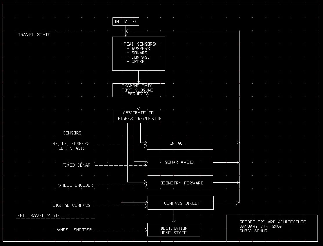
This is the behavior arbitration architecture for Geobot. What Id like you to notice here is that during the travel phase in which we are moving to and from the destination, the compass redirect behavior which constantly steers the robot toward the goal is at the bottom, and lowest in priority. This is because we have time to correct the course after reacting to impacts with rocks and avoiding small trees. Even the odometry which counts the distance traveled is more important.
Please Click thumbnail to enlarge
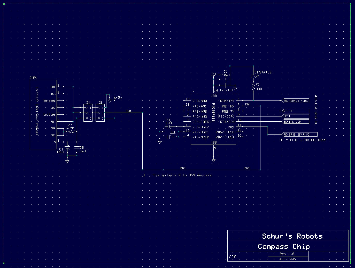
The Schematic diagram for the Compass chip. This chips purpose in life is to measure the pulse width by counting the number of 100uS intervals wide it is, and scaling it to read 0 - 359 degrees. Upon turn on, it records the bearing that you have aimed the robot at on a distant goal. It will issue directions to maintain this goal with Right and Left flag bits, and a out of tolerance bit flag. Also, if the reverse coarse input is set, the bearing will flip 180 degrees to return the robot home.
Please Click mpg movie to play
The first 160 x 100 movie clip with sound Id like to show you is a driveway test on a flat surface. The robot is turned on, and a large rock is placed directly in its path. The robot proceeds toward the rock following the magnetic bearing it read upon turn on. The rock is avoided using the quadrate sonar, and then slowly rotates back to the original bearing.
Please Click mpg movie to play
This second clip is a repeat test of the above with a different angle of attack, and the rock sitting on end. It is very important for the compass navigation to work at all angles!
Please Click mpg movie to play
Now in a moderately rocky area, the robot is aimed at the large block and avoids a large clump of weeds, then avoids the block, then returns back to its original coarse.
Please Click mpg movie to play
The BIG important movie! At the park the robot goes over a hundred feet first down a steep hill, bypassing a 6 inch concrete sidewalk edge, over the sidewalk, up a very steep hill, which triggers the over tilt sensor to cause it to back up and take a different route. Then it recovers its original bearing and after the distance drives RIGHT OVER the two green targets I aimed the robot at on the start point. The wind is really strong, so please tolerate the thundering audio!
Please Click mpg movie to play
Here is a fun shot that clearly demonstrates the compass in action. The robot is aimed at a distant tree (as best I could anyway) and the camera is put ON the robots front deck. You can see as it drives, the slow back and forth motion as the compass behavior kicks in and corrects the current bearing to within the tolerance. At the end, I jump in front of the robot, and it tries to avoid me...
Conclusion.
This is the first and important step in accomplishing the robots eventual mission: To go out a specified distance, grab some rocks, then return to start. We have demonstrated the operation and math of compass navigation, and next we will implement the turn around and return to base function. The robotic rock scoop arm is in construction and will be able to get about a handful of material to bring back.
HOME