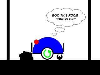

Arena is 2 x 4 foot
Picbot II and the robot Test Arena
Typically, the first sensors a robot builder installs on their new robotic creation is a frontal bumper. As to what they plan to do with these sensors is generally vague, there is little detailed information describing the behaviors to implement in the programming. Most books seem to skim over the subject – indeed, other than "Turn right for left impact" and "Turn left for right impact", most publications move on to other more enticing subjects such as sonar, or mapping. So here we wish to fill in that critical gap in information and discuss in more detail the issues that lie beyond simple "Bumper logic".
The Bumpers purpose
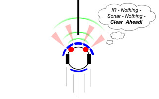
The basic explanation given for why mobile robots need instrumented bumpers is for a last line of defense type of sensor, one that takes over if the IR, sonar, or other navigational sensors fail to detect an obstacle. Or more bluntly, if your other sensors miss an obstacle, the bumper will indicate the robot has impacted with an object of unknown size and shape. The robot then can initiate some sort of evasive/escape maneuvers to hopefully get back on track to its destination.
Although many experimenters first robots are built with bumpers only for crude obstacle navigation, they are generally insufficient to keep the robot from getting trapped or stuck in a household environment. Trying to navigate from room to room with bumpers is like feeling your way in the dark, it may take your robot an excessively long time to reach its destination, if at all. That’s why we must consider adding at least IR collision avoidance after the bumpers are installed for the primary obstacle avoidance. Traditional Bumper Logic
As a minimum, two front bumper switches can be installed on the front of the robot, usually close to the ground. The general rules are:
1. Left bumper impact – Stop, turn right, continue on.
2. Right bumper impact – Stop, turn left, continue on.
This is a good formula to almost guarantee that your robot will be stuck or trapped in short order in your home environment, or even in a more controlled maze like arena like test area. First, as soon as the robot encounters a corner, it will be trapped in an endless bouncing back and forth movement until the batteries die. This is called "Canyoning" and there are a number of solutions that can be implemented to correct this condition. Second, in narrow or restricted areas, the robot can become trapped between two narrow walls, bouncing between the close walls stuck for hours, going no where. This is the "Tunnel Problem". Finally, if the robot ever backs up any appreciable distance, it can really get itself stuck since there is no way to tell that the rear of the robot has hit something. Advanced Bumper Logic
With slightly more sophisticated programming, and proper placement of a few additional bumper switches, we can avoid many of these pitfalls, and actually add some artificial intelligence to resolving the obstacle impact situation. Let us now discuss at length each condition, and some potential solutions.
How many bumpers?
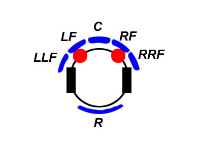
Obviously adding a continuous ring of bumper switches around the periphery of the robot is probably overkill and a waste of resources. Our experiments in normal household environments suggests five small bumper pads up front and one in the back will work optimally to make the best of a rather limited sensory net. The layout consists of a central bumper, surrounded on both sides by two side bumpers. In addition, one bumper is located on the back of the robot. We will refer to the array, which spans the full width of the robot including any wheels or projections on the sides as the following:
Left Left Front
Left Front
Center
Right Front
Right Right Front
RearBefore we define what action ("behavior") each bumper should initiate, first remember there are three types of situations we must consider. First, there is a simply reactive or reflexive behavior. This is simplified bumper logic which plays out a preset set of escape maneuvers depending on which bumper switch was depressed. These are called "ballistic" maneuvers which means once they start, they play on through to the end usually with no sensory input. An example would be: If the right bumper is hit, we first stop for half a second, turn left for 2 seconds, and continue on forward. Totally reactive, with really insignificant amounts of intelligence involved.
Second, we have chronological related impacts. This is can happen when the robot is stuck in a "canyoning" situation, and second after second the robot simply bounces back and forth trying desperately to escape. If we employ some sort of overseeing intelligence, we would detect such time dependent events and react accordingly. In this case, counting the seconds between successive impacts over a span of half a dozen impacts can flag us to the canyoning entrapment issue.
Thirdly, we add the "Creativity" factor. Recently, a professional paper I read on behavioral robotics by a psychology professor quoted him as saying "Creativity is simply a small amount random noise added to standard reflexive machine intelligence". What this amounts to is when a logical decision is made by the processor in a robot or similarly a neural net of an insect, a small amount of this random "creativity" can result in new solutions to problems at hand, and can even produce emergent behaviors. We can mathematically add randomness to our responses to achieve this. Now lets implement these three guiding processes to add some artificial intelligence to our bumper response program.
Ballistic/Reflexive Responses:
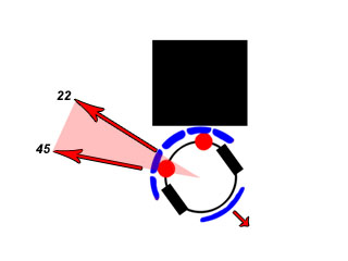
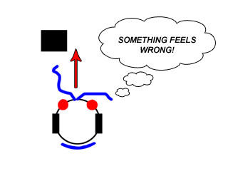
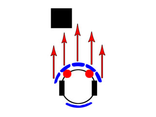
Central Frontal Impact
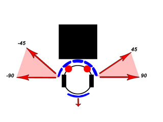
With only bumper sensors, the choice to turn right or left would be arbitrary since unlike IR, we cannot look on each side to see if it is clear. We must actually hit something to tell its there. The solution then is to first backup a small amount so that the bumper switch is no longer pressed. Then we turn right or left selected randomly with a 50% chance for each directional outcome. The maximum turn angle will be the greatest of any other bumper, and is typically 90 degrees total. Adding random creativity here is essential so we do not end up in the same predicament twice. For our robot, we chose to rotate 45 degrees plus a randomly selected amount ranging from 0 to 45 degrees giving the total possible as the desired 90 degrees.
Right and Left of Center Impact
On each side of the central bumper, we have the adjacent bumper switches. These of course are on an angle of about 22 degrees, as the body curves around the robot. As we move out from center, the total amount to turn decreases proportionately. This is to keep the robot heading generally in the same direction it started before the impact. This we call "proportional reactivity". For these bumpers, we first stop forward motion, back up to release the bumper switches and then rotate in the opposite direction of the impact by a total of approximately 45 degrees. Again, incorporating random creativity will ensure we don't oscillate back and forth in the same way in tight situations. So we rotate 22 degrees, and add a random amount of 0 to 23 degrees for a total of 45 degrees of rotation.
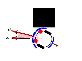
Far Right and Far Left of Center Impact
The outside front bumpers indicate a skimming impact to the sides of the robot. Reaction will be minimal such that the robot can traverse narrow corridors if needed. The robot will stop, and back up about half as much as we do on a central impact. This is because the angle of the side bumpers will be near 45 degrees to forward normal and less distance is needed to clear skimming impacts. We then rotate right or left opposite the impact a total of 22 degrees. This consists again of half fixed and half random. In this case, if we rotate 11 degrees plus a random amount between 0 and 11 degrees will be about right. For these bumpers, you may wish to trim this down a bit so increase the tightness of how well it can traverse a corridor or hallway.
Rear impact
The rear bumper, which has extensions such as whiskers or a curved bumper rail can be simply one switch. This is because most robots only move backwards rarely any appreciable distance, and only when performing some sort of evasive maneuver, or a controlled docking procedure. The key is to run a loop during the back up move such that we watch out for a rear impact, and stop backing up. So our inch or two we back up for a frontal impact may be truncated to less than an inch in tight situations. A rear impact by itself won't cause a reaction, only when we are purposely backing up do we watch this sensor.
Time/Event Responses:In addition to purely reactive responses, there are responses to events in which occur over a period of time in which we must respond to. For example, if we receive half a dozen bumper hits over a period of say five seconds, we can be certain that we are trapped in a narrow confining space. By watching the times between impacts, we can detect such episodes and take evasive action.
Rapid multiple impacts
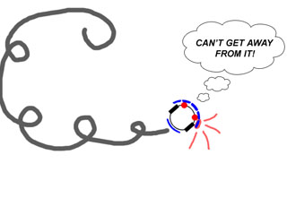
There are two main types of time correlateable impact events which we can get into. Both result in multiple impacts over a short time interval, and telling them apart is not always easy. The response to each type is a bit different and are discussed below."Canyoning" (Corner entrapment)
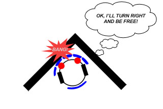
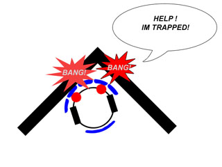
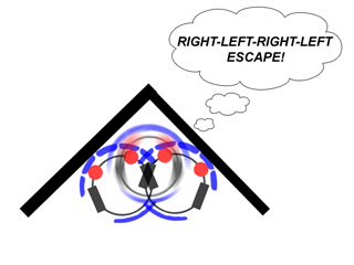
This is the most common type of time correlated impact event robot experimenters encounter. In this case, the robot will become trapped in a corner of a room, or parts of furniture at the correct spacing by bouncing back and forth between adjacent walls. For example, when a robot hits the corner with its left bumper, it turns right evasively. But then a second later, it hits on the adjacent wall with its right bumper and then turns left evasively. This can go on indefinitely until the robots batteries run flat. Detecting and correcting this condition is of major importance if we expect the robot to function in a household environment. To correct this condition, we first have to detect it. This is done by recording the last four impact events in memory, and the time between them. Then we examine the times and direction to detect "canyoning".
Its probably 99 percent effective at corner escape. You may also record the direction of the turn as well. A corner will record as: Right-Left-Right-Left or its inverse. If this occurs AND your time sum is short, then you are certain you are trapped in a corner.
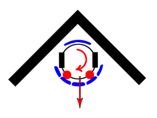
To implement this method, we will program the robot to remember. This is not difficult, and introduces the concept of learning matrixes. The basic idea is to set aside four or more variables that will be used to store timing data. While the robot is moving forward and not hitting anything, we constantly count a small time interval, for example, 10mS increments. This is small enough not to upset any rapid responses to impacts. Then when we detect a bumper impact, we respond as usual, but record the last time that the loop counted and reset the counter. After each successive impact, we continue to shift the old readings down a notch and record the new one. So we get a running total of time between the last four impact times. Then after every impact, we take a quick look at the list of for variables, which is really a 1 x 4 array. If the sum is less than 5 seconds or less, than the rapid impact condition has been detected. For most cases this will suffice to escape the corner by rotating 180 degrees.
Here is some example pseudo code to detect most corners:LOOP:
Test bumpers
IF impact Then EscapePAUSE 10mS
T = T + 10 ‘Count 10mS increments of timeGOTO LOOP ‘No impact
ESCAPE: ‘Shift down values in array T3 = T2 T2 = T1 T1 = T0 T0 = T IF T0+T1+T2+T3 < 5 Seconds THEN CORNER Perform escape maneuver GOTO LOOPCORNER:
Rotate 180 degrees
GOTO LOOP
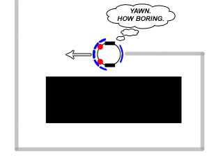
Left: Escaping a corner
Of course you will have to add a few lines to limit the range of T as it rolls over in the count and such. But that’s the basic idea. But there may be one case that appears to be a corner to a bumper only equipped robot, but it still may not escape from. That is "Tunnel Entrapment".
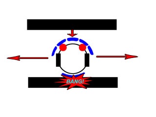
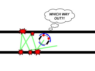
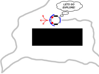
Tunnel Entrapment (Narrow Corridor entrapment)
Without the aid of IR or Sonar to look for the furthest route for escape, navigation with bumpers only can be quite trying at times. One last condition to look out for is Tunnel entrapment, or "Tunneling" for short. Imagine your robot enters a narrow hallway or space between the couch and back wall. Somewhere in the middle the robot will start impacting the walls. What ensues after that depends a lot on the shape of the robot as well as how much clearance it has, but the most likely outcome is that the robot will starts bouncing from wall to wall very quickly, and get stuck. Since it can detect an object unless it hits it, it is hard to tell which way will lead the robot out of the tunnel. Many home robots will run fine for hours inside a house, and then tunneling occurs, trapping the robot until its batteries run out. Tunneling looks an awful lot like Canyoning to a robot equipped with a bumper only. But there are differences that can be looked for and a very different approach to escape can be implemented.
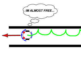
To detect Tunneling, we not only must record the last half dozen or more impact time spacings, but also how often the corner escape response is activated. After two or three corner escape responses have occurred that are closely spaced, and the robot is still getting nowhere, we implement our tunnel escape routine. While this is not a foolproof method, it may get the robot out of some potentially fatal entrapments. The response of course is to "wall follow" your way out. In wall following we continue to turn toward the right or left side gradually, and only turn away upon impact a tiny amount. This will make the robot follow the walls or corridor sides in a series of small arcing paths. The wall following ends when any other bumper encounters an impact, perhaps an indication of the end of the tunnel.Some Pseudo Code for tunneling escape might look like this:
LOOP:
.
(same as code in above example)
.
GOTO LOOPCORNER:
Test time between last three times we visited here
IF SUM < 10 seconds THEN TUNNEL
GOTO LOOPTUNNEL:
Wall follow until impact
GOTO LOOP
The main technique for bumper wall following is to ensure that the bumpers protrude out from the sides of the bumper array to be certain that an impact with the robot nearly parallel to the wall will be detected. The size of the arcs is determined by how sharply you turn back into the wall. Too wide, and you may miss a curving wall. Too narrow and you will expend a great deal of energy bouncing off the walls. An arc of six inches to several feet is appropriate, and depends greatly on the length of the runs in the household against the walls. In our small robot test arena, we set the distance to around six inches to hug the walls tightly. The only caution I would extend to you here, is to make sure the wall following escape is time limited, say to 5 seconds max. Otherwise you may find your robot wall following a round piece of furniture for a very long time!
It should be obvious that feeling your way around a room with bumpers is risky at best, there are so many ways to get stuck its hard to plan for all conditions, let alone detect that condition exists. But good programming practice here will be a great backup for the IR and other sensors if they should fail.
Stasis (Lack of any impacts)
Another aspect of any escape plan Is to plan for the stasis escape events. Here is how it works. Lets say the area a robot will be traveling in between destinations will be a certain size, like 20 feet square. Now if a robot travels for a time longer than the time it normally takes to cross the entire room with no bumper impacts, it may be stuck with wheels turning and the bumper may not reach or touch the obstacle. At that point, we can implement the Stasis escape routine, which will back the robot out by waddling each wheel in turn to work its way loose. This can be a ballistic routine – we run through the timed response without looking at the bumpers. To implement a stasis escape, We use a running total of the on time between bumper hits. If we reach a specific total for example, we probably are in a stasis entrapment. An example of pseudo code is like this:
LOOP:Test bumpers
IF impact Then EscapePAUSE 10mS
T = T + 10 ‘Count 10mS increments of time
IF T > 1500 THEN STASIS ‘over 15 seconds no hitsGOTO LOOP ‘No impact
STASIS:
Stasis escape routine
GOTO LOOP
False Positives (Bumper stuck on)
A common problem with home brew bumper switches is that the robot designer used the switches lever itself as the support for the bumper or feeler. This will not last long, and can result in either a jammed stuck bumper switch or a bent switch lever. Also occasionally, switches will fail from use. Either way, when a single bumper switch gets stuck on, the robot will respond constantly, driving in circles trying to escape the phantom obstacle. Monitoring the on time of each bumper can alert the processor if the on time is excessive, such as 5 seconds or more. Also, if you record the last ten directions turned and they are all ways the same, that’s a pretty good indication to take notice. Another technique is to look at the bumper after backing up upon a normal frontal impact. It should be no longer indicating an impact, unless it is stuck on. There is little that can be done to unstick the bumper while the robot is roaming, but we can have the robot ignore the stuck bumper or alert the operator if it exceeds the closed threshold time. False Negatives (Bumper switch bad)
This one is hard to detect, if a bumper switch goes bad and no longer closes. This can occur also when the bumper is actually tore off during an escape episode. You may have to look a long time to see if there is no response from a given bumper. If it is the center bumper, the robot will probably stop with wheels turning and the stasis detection may kick in. But a side bumper is more problematical. A possible solution is to have the robot periodically test the bumpers against an obstacle by rotating the specific angle between them and driving forward to look for an impact on a specific bumper. This might be done on initial power on, at the robots base.
Creative Responses
We are maintaining the definition of robot "creativity" as a small amount of random noise added to reflexive responses. Such a concept is used in biological systems for generation of novel solutions to everyday problems. An example in the biological world would be a deer walking through a forest. When the deer comes up to a large tree, it must go around it. But which way? After some moments of contemplation, the deer seemingly randomly chooses a direction and continues on. Randomness can be used for discovery as well. Consider an ant heading toward a known food source. As the ant moves forward, its path wanders back and forth randomly as the random noise in its leg movements cause it to go astray. When the ant nears its destination, it discovers a second food source, that was just off the beaten path along the way. We can employ random noise in this biomimetic sense to improve the escape and search routines in home robots.
Defining Random noise
There are several methods for generation of random noise with software. Pbasic and PICbasic have the "RANDOM(X) command which basically shuffles a seed number up a bit. You can also generate a fairly random number by taking the non integer portion of x = y^3, a technique which has been around for many years. Pulling randomly generated numbers from a look up table is a bit quaint, but still can work in a limited way. To test a "random" number generator to see how random it really is, you can take their average, and it should after increasing number of generations to half the max – min values. In other words, Av = Sigma min to max/n. For most software, that will be around half of 8 or 16 bits, or around 128 or 32,500.Generation of random "Creative Responses"
So far, we have seen a great application of creative response used in our rotation algorithms for each bumper. By adding a small amount of range limited randomness to the strictly reactive Right/Left response upon obstacle impact, we can in fact use this not only to help us get out of sticky situations, but it will for certain eventually work us out of Canyoning entrapment, and possibly Tunnel entrapment situations. If we layer upon that some AI that actually looks for those entrapment situations as well, we can increase our escape chances dramatically.Applications for "Creativity"
There are so many uses for this useful concept, I will only cover it as far as our bumper logic is concerned. Key here is after deciding the maximum turn angle of the robot after a specific impact, we divide that amount in two, and make the second half a random number that varies from zero to half your maximum to complete the full angle. So in the case of a right impact for example, we will turn left no more than 90 degrees, but always more than 45 degrees by adding a fixed angle of 45 to the random variable with a range from 0 to 45 degrees. After all, we do want the robot to keep going as much as possible the original direction it was going to reach a specific goal! Not recommended is turning randomly all the time, 0 – 360 degrees will certainly get a robot out of many situations, but like a toy with no purpose, it will simply bounce around the room at random only reaching the goals by chance. We can also use the "creative" concept for time correlated situations. A little random time added to wall following or backing up can result in some very useful solutions that may not have been achieved otherwise. Bumper electro mechanical architecture
Here we discuss the electro-mechanical implementation of the robots bumper array. First and foremost, you must come to the realization that the proper concept for what we are trying to build is not a set of switches with a bumper plates attached. What we are making is an "Instrumented Bumper". There is a huge difference in design philosophy. The incorrect way to design this impact detection system is to mount switches on the front and rear of the robot, and attach some sort of wire, bar or panel to the switch levers or buttons. Although this may work for the short term, it is unreliable in the long run and will quickly wear out or bend the switch mechanism to destroy or make it otherwise useless. The correct scenario for a proper impact detection sensor is as follows:- First, design a multi-section rugged mechanical bumper system for the front and rear of the robot.
- Second, add the detector switches to the bumper.The logic behind this is to construct a strong, range limited set of bumper plates or bars that can take the mechanical stresses they will see in the real world. By limiting the range of the mechanical assembly, we can in fact prevent any possible damage to the sensory switches.
Lets give some examples of bad and good impact bumpers. How many robots have you seen that bolt or glue (egad!) lever switches on the front, and attach music wire whiskers to the levers with some sort of plastic tubing? Lots I’m sure. After a few dozen smacks into the walls and furniture, the levers become distorted, and the push buttons bottom out hard enough to damage them. Even worse, because the back wards bending is not limited, when the catch on obstacles when turning, they actually bend the levers outwards at the very hinges, and never return to normal. This is a POOR design. Now lets consider another type. The entire robot is surrounded by a plastic or metal cylinder, suspended at the top by music wire or the likes of. In the gap between body of the robot and the inside of the cylinder, we mount several lever switches around the periphery, such that when the cylinder encounters an obstacle, it swings inwards and closes a nearby switch and therefore yielding some directional information. In addition, we mount on each side of the switches a short peg, that the cylinder will bottom out on before it crushes the switch levers completely. Alternately, we can recess the body of the switches such that only the levers protrude. We have now limited the motion mechanically, and THEN instrumented the inside edge with crush proof (the pegs) switches. The "Rug Warrior" robots sold to many today uses this concept. This is a very GOOD design.
There are numerous other minor details in bumper construction that will make them optimal in the detection of impacts such as adding rubber pads to avoid damage, or splitting the bumper into sections to provide more sensory information. Spend some time looking at the "Robot Menu" photo pictorial on Robots.net for ideas that apply to your environment. You will see both good and bad designs, but there are lots of great ideas there to be seen.
Finally, we should discuss bumper sensory layout. Most roboticist agree that a round body with differential steering is the best design for an indoor home robot, with a size certainly less than a foot in diameter. This allows the robot to rotate in place when moving about and avoiding obstacles while not catching corners and projections on the robot on furniture and such. Your robot can actually be square or rectangular too, as long as its outer skin or boundary defined by the bumper ring is round. This is very commonly done as well to get the best of both worlds.In our home dwelling robots, we have decided on five front bumper plates and one rear. This was not an arbitrary choice, but worked out through dozens of robots over the years operating in both indoor and outdoor environments. You can of coarse have how many you wish, but just remember that one or two frontal bumpers is never enough to keep you out of trouble in our experience.
Summing it all up
Designing a bumper array and programming for it is a straight forward, and methodical task. Try to avoid the pitfalls of poor designs, and don't try to over simplify the somewhat complex behaviors that a good solid instrumented bumper design will exhibit. We hope by showing you some of the details of what we have done in the past years in this field will open your eyes to be at least more cautious and intelligent on your own designs, and perhaps provide some guidance on the implementation and programming as well. If we can help just one budding robotics builder create a better and more intelligent machine, then we have accomplished our task!
Chris Schur
October 12th, 2006