Robot Color Sensor - 1

Updated 8/18/16

Key Search Words: PIC Microcontroller, CCS C Compiler, PIC Projects


Introduction: 

Here is my first attempt at a device which measures the color of a flat surface below the sensor, and bins it into Red, Blue, Green, White or Black. The purpose is to mount this sensor on a mobile robot, and have the robot use the color information on the ground below it to make intelligent decisions about its tasks. An example might be a particular location in the arena, or the amount of water to put on a special plant.

Concept for sensor:

The sensor consists of three broadband visual wavelength photocells with red, blue and green filters surrounding a 3200K white LED for illumination of the target. After a calibration on a white surface as a reference, the sensor voltages for each color are proportional to the color filters. So for a white target, the readings are the same, since white is equal combinations of all three colors red, blue and green. For a colored target such as red, the red channel will read higher under illumination than the blue or green so we can deduce the color chips color by identifying the brightest reading. For black, all colors are very low in brightness. A micro controller calibrates, reads and displays the results of each measurement, which takes around 1/3 of a second and sends it to both a LCD display and three LED's that are colored the same as the filters.

Program sequence:

The processor, a PIC16F876a chip first turns on the white light and allows 300ms for the sensors which are cadmium sulfide to stabilize. Then it reads all three sensors which are part of a voltage divider with a 4.7k and put out a very low voltage in dim light, and a maximum voltage in full illumination. Most readings are from 1 - 3v into the 10 bit A/D converters. The readings are then normalized by determining the multipliers for the blue and red light to equal the green reading. This will be applied to all subsequent readings. Then it reads out continuously allowing the mandatory 300ms to elapse after light turn on to stabilize the CdS. The robot will read the parallel outputs for the RGB LEDs and then know the color under the robot at that time. For now, we can see the lamps light accordingly.

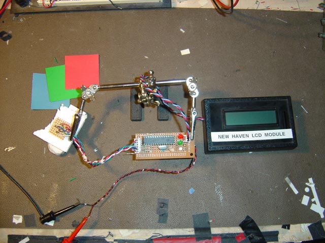
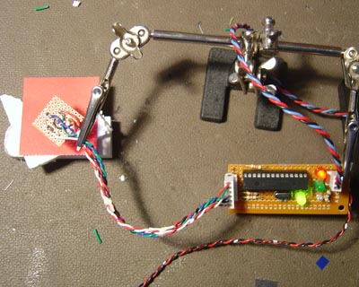
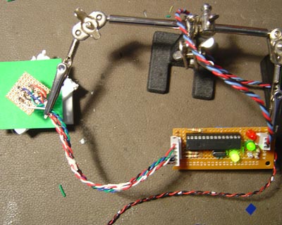
Bench setup. On the right is the LCD display for seeing the actual RGB values. The center is the board with the processor and to the left the sensor board is held half an inch over a white Styrofoam target. Styrofoam is a very uniform reflector for all colors from IR to UV. The color chips are construction paper and can be seen above. To the right of the chip are the three color LEDs.
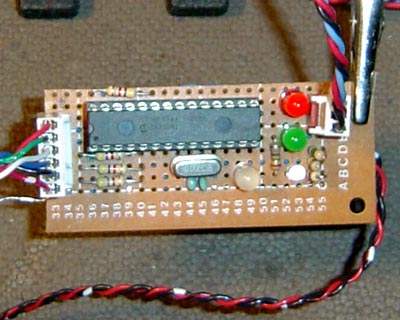
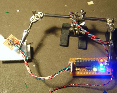
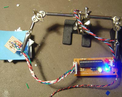
Micro controller board. Im using a red, green, and blue LED on the right to indicate color maximums. the crystal is 10Mhz.
Schematic for the micro board and sensor. Click to see full size.

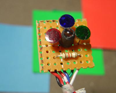
Color sensor head. The 3200K white LED in center puts out more reds and is relatively visual in output color. The filters are made by using a paper punch and making disks out of gel filters. The filters used are W25 - Red, W58 - Green, and W47 - Blue. Differentiating blue and green is not easy...

Also note the black sleeve around the white LED in the center. This keeps the side light from fogging the photocells.

Response time of CdS photocells. It takes roughly 200 - 300ms to stabilize once the LED lights up and shuts off. This has to be added to the read sequence to keep all accurate!
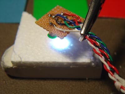
Sensor over target with white light on. On the robot, the sensor will be housed in a black cylinder (read: bottle cap) to keep ambient light out.
RED chip - see top red LED is on.
GREEN chip - see middle LED is on.
BLUE chip - see blue bottom LED is on. (way too bright here)
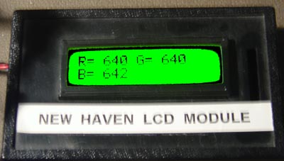
LCD readout of white surface.

White surface - all three LEDS are on.


The next step is to mount this on the whisker bot and see what we can do!

CCS - C code for processor: //**************************************************************************** //Chris Schur //(Color Sensor - my design 16F876a) //Date: 8/5/16 //**************************************************************************** /*Description of this Program: This version reads sensors, and lights LEDs and sends to LCD. */ //I/O Designations --------------------------------------------------- // RA0: Analog input An0 - RED photocell // RA1: Analog input An0 - GREEN photocell // RA2: Analog input An0 - BLUE photocell // RA3: // RA4: (Open Collector output) // RA5: // RB0: // RB1: OUTPUT - WHITE CAL BICOLOR LED // RB2: OUTPUT - WHITE ILLUMINATION LED // RB3: OUTPUT - WHITE CAL BICOLOR LED // RB4: // RB5: OUTPUT - RED STATUS LED // RB6: OUTPUT - GRN STATUS LED // RB7: OUTPUT - BLU STATUS LED // RC0: OUTPUT - LCD SERIAL OUT // RC1: // RC2: // RC3: // RC4: // RC5: // RC6: // RC7: //-------------------------------------------------------------------- //Include Files: #include <16F876A.h> //Normally chip, math, etc. used is here. //Directives and Defines: #device ADC=10 //Set ADC when used to 10 bit = 0 - 1023 #fuses NOPROTECT,HS,NOWDT //xtal is used #use delay(crystal=10MHz) //xtal speed #use fast_io(ALL) //must define tris below in main when using this #include <stdlib.h> //for abs function. //for LCD: #use rs232(baud=9600, xmit=Pin_C0, bits=8, parity=N,stream=SERIALNH) //NO_ANALOGS is default in device file... //Defines: #define RED (Pin_B5); #define GREEN (Pin_B6); #define BLUE (Pin_B7); #define WHITE (Pin_B2); #define CALP (Pin_B1); #define CALN (Pin_B3); //**************************************************************************** //Global Variables: signed int16 Rresult; //a/d raw readings for each photocell signed int16 Gresult; signed int16 Bresult; int16 Rabs; //absolute value of G - R int16 Babs; //absolute value of G - B float Rfactor; //multipliers for normalize RED to green. float Bfactor; //multipliers for normalize Blue to green. //**************************************************************************** //Functions/Subroutines, Prototypes: void LCDCLR(); //Clears LCD Display: void LCDLN2(); //Sets LCD to line 2 start point void GETDATA(); //Takes sensor data and saves. //**************************************************************************** //-- Main Program //**************************************************************************** void main(void) { // Set TRIS I/O directions, define analog inputs, compartors: set_tris_A(0b11111); set_tris_B(0b00010001); set_tris_C(0b11111110); //Initialize variables and Outputs: -------------------------------------- //Turn off all LEDS output_low WHITE; output_low RED; output_low GREEN; output_low BLUE; //set cal LED to red.-> it will turn green when white cal is completed. output_low CALP; output_high CALN; //Now set up A/Dconverter: setup_adc_ports(ALL_ANALOG); //AN0 - AN4 sensor v input is 0 - 5v setup_adc(ADC_CLOCK_DIV_32); delay_ms(1000); //LCD warmup time //SET BRIGHTNESS OF LCD TO MID RANGE. (DEFAULT = 1) fputc(0xFE,SERIALNH); //Command Prefix fputc(0x53,SERIALNH); //set cursor command fputc(8,SERIALNH); //4 is mid 0-8 delay_ms(250); LCDCLR(); delay_ms(250); fprintf(SERIALNH,"COLOR-1"); delay_ms(25); LCDLN2(); fprintf(SERIALNH,"READY"); delay_ms(1000); //display time. //---------------------------------------------------------------- //MAIN LOOP: //first get raw data anc calculate normalization values: GETDATA(); Rfactor = ((float)Gresult / (float)Rresult); //Calculate floating number for normzing. Bfactor = ((float)Gresult / (float)Bresult); // for normzing. //Light cal lamp green if cal factors less than 2:(if cal factor is huge, then something //really bad went wrong) if ((Rfactor <=2) && (Bfactor <= 2)) { output_low CALN; output_high CALP; } //Now we start taking contiuous readings and sending to both LCD and LEDs. while (true) { LCDCLR(); delay_ms(25); GETDATA(); Rresult = Rresult * Rfactor; //normalize to green. Bresult = Bresult * Bfactor; //calculate differences to see if we are looking at a white target. Rabs = abs(Gresult - Rresult); Babs = abs(Gresult - Bresult); if ((Rresult < 100) && (Gresult < 100) && (Bresult < 100)) { output_low RED; output_low GREEN; output_low BLUE; goto DISPLAY; } //skip lighting LEDs if no data is valid. //now light appropriate color led indicator: if ((Rresult > Gresult) && (Rresult > Bresult) && (Rabs > 10) && (Babs > 10)) { output_high RED; output_low GREEN; output_low BLUE; } if ((Gresult > Rresult) && (Gresult > Bresult) && (Rabs > 10) && (Babs > 10)) { output_low RED; output_high GREEN; output_low BLUE; } if ((Bresult > Rresult) && (Bresult > Gresult) && (Rabs > 10) && (Babs > 10)) { output_low RED; output_low GREEN; output_high BLUE; } //otherwise: if ((Rabs <= 10) && (Babs <= 10)) { //This means you are still looking at WHITE. output_high RED; output_high GREEN; output_high BLUE; } DISPLAY:; //Now send to LCD: fprintf(SERIALNH,"R= %Lu",Rresult); delay_ms(15); fprintf(SERIALNH," G= %Lu",Gresult); LCDLN2(); delay_ms(15); fprintf(SERIALNH,"B= %Lu",Bresult); //fprintf(SERIALNH," %Lu",Rabs); //fprintf(SERIALNH," %Lu",Babs); delay_ms(250); //display time } } //********* Functions which have prototypes at top of program **************** void LCDCLR() { fputc(0xFE,SERIALNH); //Command Prefix fputc(0x51,SERIALNH); //Clear screen } //Sets LCD to line 2 start point void LCDLN2() { fputc(0xFE,SERIALNH); //Command Prefix fputc(0x45,SERIALNH); //set cursor command fputc(0x40,SERIALNH); //Set cursor to next line, pos 40 = start line 2 } //Takes sensor data and saves. void GETDATA() { output_high WHITE; //Turn on white LED illumination. delay_ms(300); //stabilize - CdS takes 300ms to reach final value. //RED reading: set_adc_channel(0); delay_ms(10); Rresult = read_adc(); //GREEN reading: set_adc_channel(1); delay_ms(10); Gresult = read_adc(); //BLUE reading: set_adc_channel(2); delay_ms(10); Bresult = read_adc(); output_low WHITE; //Turn off white LED lamp. }
HOME