
Wintertime is harsh on indoor plants. The lighting from the Sun is far less intense, and only a few hours each day does the it shine through the Arcadia doors to light our robot tended garden. (See Cbot-1). My plan was to supplement the daily Sun light with a high intensity overhead plant light, using LED technology. An extra few hours per day starting at sunset is all they (Bell Peppers) will need to keep growing strong through the winter months. It is currently set for an extra 4 hours per day on time, then the plant has its essential rest period in darkness for the rest of the night.
About LED Plant Lights
For decades now, indoor growers in green houses and warehouse facilities have used halogen lighting for their indoor growing needs. They are very hot, draw huge amounts of power and not only can roast the plants, they waste so much electricity that the price of the product is highly influenced by the use of them. When LED's came on the market about a decade ago for an alternative lighting solution, they were accepted by many as the cost effective solution, and would not burn the plants. Interestingly enough as you will see, plants do not require all the wavelengths put out by the Sun - they dont need any pure green, only a touch of IR, and as little of UV as possible. Plants are green because they reflect this color away to avoid overheating and maximize the chlorophyll conversion efficiency. They DO need blue, red, and cyan (blue/green) to grow properly. Since I am supplementing the Sun, I need not worry too much about the exact ratios or how much green light is present.
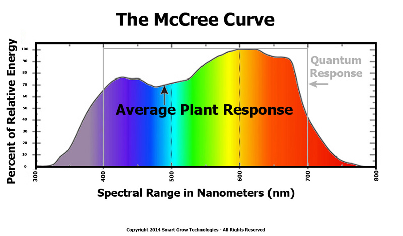
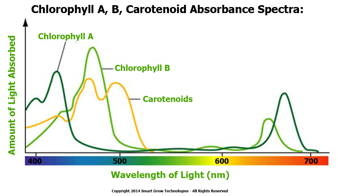
Some plant absorption spectra:
This is a very generalized curve on plant absorption over the visual range of wavelengths. Obviously a lot of red and blue, with less green and cyan is indicated.
Breaking it down into the food producing components in the leaves, we find that while chlorophyll requires both red and blue light, the carotenoids will require a bit of cyan. The Blue LED does indeed put out a bit of cyan light, and the daily dose of the Sun will fill in the rest. So for our plant light, only blue and red is essential.
Initial concepts and design:
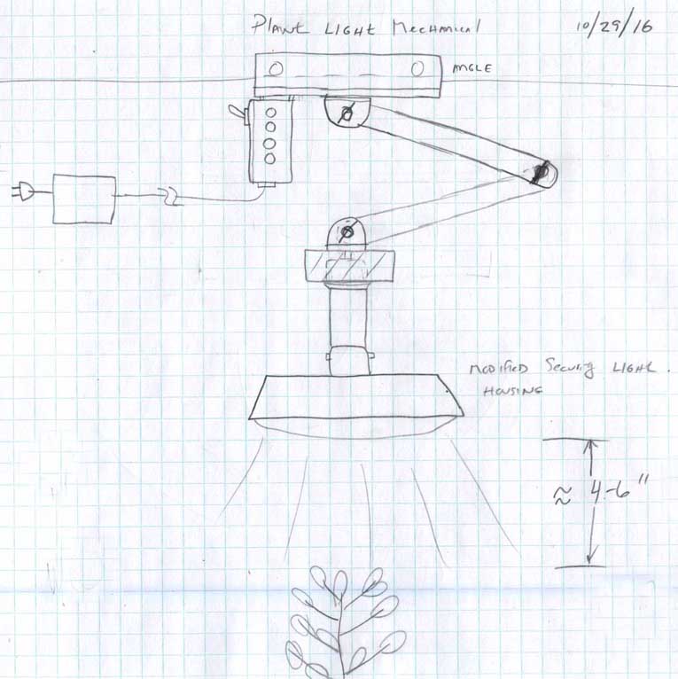
Click to Enlarge to full size Here is my original concept sketch of what I was planning. An old LED security lamp was to be gutted and hold the red and blue LED's. A 2 foot adjustable arm would allow precise positioning over the desired set of plants. At the top, an angle allowed the use of a simple C clamp to connect to a shelf or table. Finally, the electronics box is mounted on the top and displays the various modes of operation as they do their daily run.
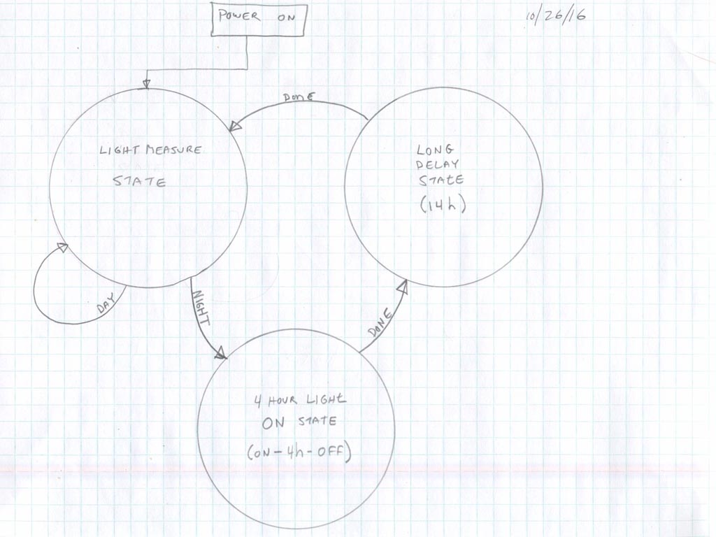
Click to Enlarge to full size At first thought, the plant light operation has two modes - Light ON, and Light OFF. But in reality to make the timing coincide with sunset and include the 4 hours of on time, we need THREE states. This is how you rough out a micro controllers program to set up how the device will operate. There are three stable modes of operation. A "Light Measure State" for the daytime when the lamp is off. It just keeps looking for dark all day long. When found (with a simple photocell) it jumps state to the "4 hour Light ON State". Here we turn on the big lamp, start the timer and wait 4 hours. When thats done, we jump state again.
Now we go to the third state - the "Long Delay State" which is 14 hours long. Thats all it does, waits 14h and then jumps out back to the first state. This crucial state allows the night to pass, and it usually comes out of this state around noon the next day - when its plenty of daylight. Then were back to looking for night again. Over and over, day after day - this is its task.
Click to Enlarge to full size
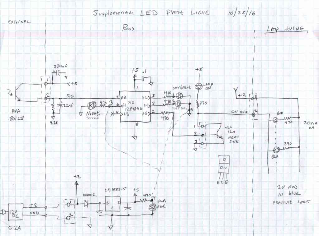
Schematic of whats in the box. My favorite processor the PIC12F1840 is a small 8 pin device which does everything you can possibly fit into such a small processor. The data sheet is over 100 pages long! All this for one dollar. It reads the phototransistor output as a 0 - 5v signal, and when it drops below a count of 30 out of 1024 values, its considered night. Various status LED's are also lit so I can track its progress through the program. A 12v external power supply is regulated to 5v with an LDR. For turning on the power hungry LED lamp which draws 700ma, I use a TIP120 power darlington transistor mounted on a small heat sink. It hardly gets warm.
Building the hardware:
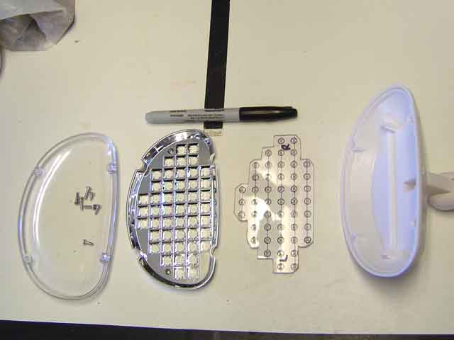
Here is the components of the security lamp I used to mount the color LED's in. I pulled the circuit board they had out with its gobs of tiny white LED's and made a 1/8" lexan board with holes drilled out for the legs of the parts to fit inside where the board was. The housing is a white acrylic plastic, with an adjustable joint (right) and contains a chromed reflector matrix for around the lamps, and a clear protective cover.
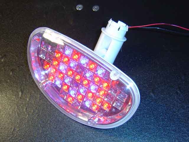
With the color LED's mounted up and soldered together, each with its own series resistor (470 and 390 ohms) the lamp puts out the required balance of light - 70% red, and 30% blue light.
For better diffusion, I ground every LED on the front with a flat to spread out the light further and not project a hot spot.
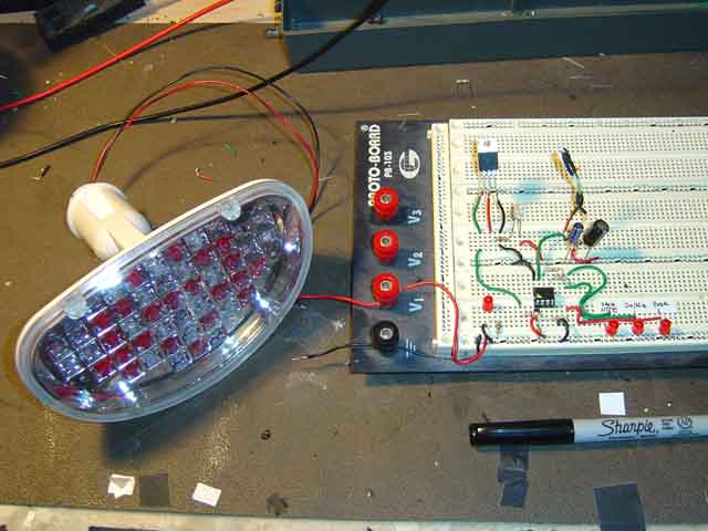
Testing breadboard for the processor and associated components. All the software is written at this stage, so upon final assembly its ready to go.
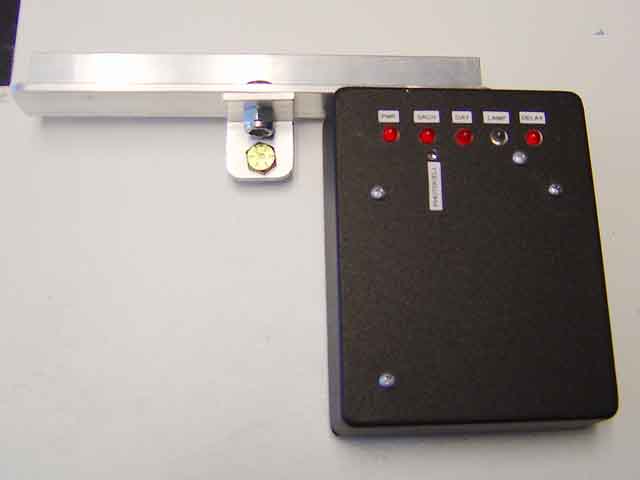
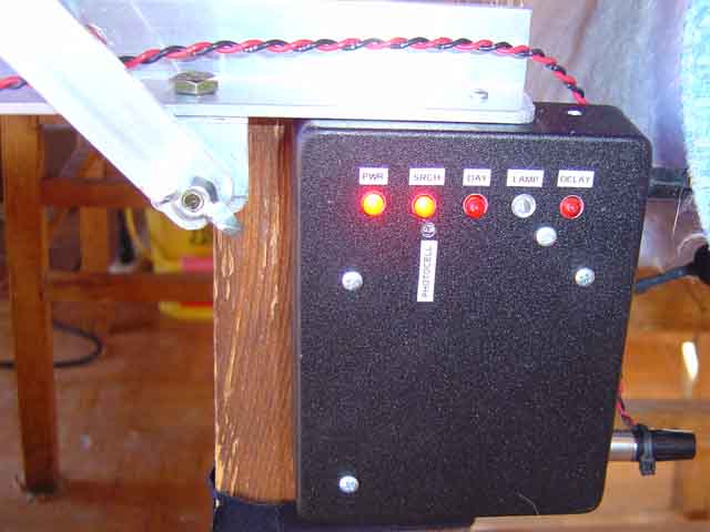
The electronics were then mounted on a small 2 x 3 board and installed in this metal box. This is bolted to the top bracket for the lamp arm. The LED's on the box show the states the program is in during operation. The photocell is the extra hole below the second LED.
In operation, here it is searching for darkness in the first FSM state. On the right side is connectors for both 12v power, and lamp output to the big lamp.
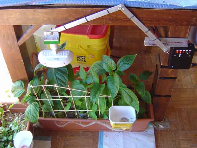
The entire assembly is C-clamped to the leg of the dining room table and wires dressed down nicely with velcro strips. (Giant rolls of velcro at Home Depot)
The pepper plants have done well since their planting in early August of this year. The robot waters them once per day at sunrise. The same type of algorithm is used to detect sunrise and send the robot off on its three planter watering mission each morning. If you would like, the write up on the Plant watering robot can be found here.
The robot essentially pours water using a pump and on board water tank into the funnels on each planter. Then it goes back and refills itself for the next days task. These are truly hi-tech pepper plants!
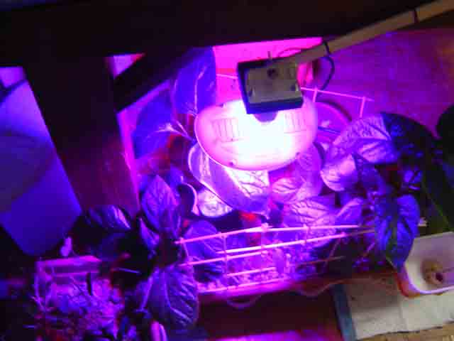
At dusk, the plant light goes on. It is a very peculiar color for sure! The plants leaves appear nearly black under this light. Can you guess why?
Right now, only half the planter gets the supplemental light. I want to see how the plants do compared to the unsupplemented portion on the right after a few months.
Code for this project using CCS-C into the PIC12F1840 processor:
//****************************************************************************
//Chris Schur
//(Plant Light): 12F1840
//Date: 10/28/16
//****************************************************************************/*Description: This program will light the high intensity plant light when it
is night time for four hours or so then turn off looking for day again.
*/
//I/O Designations ---------------------------------------------------
// A0 (RA0): Analog input - Photocell
// A1 (RA1): Output - Day/Night Search LED
// A2 (RA2): Output - Day/Night LED
// A3 (RA3): X (can ONLY be input)
// A4 (RA4): Output - Post Delay LED
// A5 (RA5): Output - Lamp ON Array//--------------------------------------------------------------------
//Include Files:
#include <12F1840.h> //Normally chip, math, etc. used is here.//Directives and Defines:
#device ADC=10
#fuses NOPROTECT,NOMCLR
#use delay(internal=4000000) //Use internal clock, no Xtal
#use fast_io(A)//****************************************************************************
//Global Variables:
//****************************************************************************
int16 result; //0 - 1023 out of ADC
int8 fsm; //finite state
int16 n; //time counting var.
//****************************************************************************
//-- Main Program
//****************************************************************************void main(void) {
// Set TRIS I/O directions, define analog inputs, compartors:
//(analog inputs digital by default)
set_tris_A(0b001001);
//(analog inputs digital by default)
setup_adc_ports(sAN0);
setup_adc(ADC_CLOCK_DIV_32);
set_adc_channel(0);//Initialize variables and Outputs: --------------------------------------
output_low(PIN_A1);
output_low(PIN_A2);
output_low(PIN_A4);
output_low(PIN_A5);
fsm = 0; //initial state upon turn on
//----------------------------------------------------------------delay_ms(2000);
//MAIN LOOP:
while(true) {//FSM for operation
switch (fsm) {case 0: //LIGHT MEASURE STATE
//Here we measure the photocell, if its day we stay here, if its night
//we jump to state 1.
output_low(PIN_A4); //turn off post delay lite
//First we read the photocell:
result = read_adc(); //take analog reading. 5v=day, 0v=niteif (result >= 10) { //daytime
output_high(PIN_A2);
output_high(PIN_A1);
delay_ms(1000); //take readings periodically lookin for night
output_low(PIN_A1); //blink night search LED
delay_ms(500);
fsm = 0; } //stay here until night, keep looking.
if (result < 10) { //nighttime
output_low(PIN_A2);
fsm = 1; } //jump state, its night now.
break;
case 1: //LIGHT ON STATE
//Simple - turn on the big lamps for 4 hours, then jump to state 2
output_low(PIN_A1); //no longer searching for night
output_high(PIN_A5); //turn on plant light
//now 4 hour delay:
//delay_ms(3000); //short test delay of 3s
//for(n=1; n<2; n++) { //1 mins test delay
for(n=1; n<240; n++) { //240 mins For 4H delay
delay_ms(60000); } //one minute delay = 60,000 mS.
//turn off plant lamp:
output_low(Pin_A5);
fsm = 2; //jump state to post light long delay...
break;
case 2: //LONG DELAY STATE
//Here we delay after lamps turn off until it will be day time (~14h)
//then jump back to state 1.
output_high(PIN_A4); //post delay lamp
//14 hour delay now:
//delay_ms(5000); //5s test delay
//for(n=1; n<2; n++) { //1 mins test delay
for(n=1; n<840; n++) { //840 mins For 14H delay
delay_ms(60000); } //one minute delay = 60,000 mS.
//ok, its daytime now, youve waited long enough
fsm = 0; //done, jump back to light measure state look for night.
break;} //switch
} //while
} //main