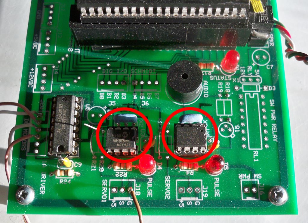

Above: This set of two motor drivers is now installed on our new Robot processor board. Each one drives a separate motor. Its always great fun to find new ways to use the least expensive PIC's for home robotics experiments and projects. Here, I use one of the cheapest PIC microcontrollers, the venerable 12F629 device, an 8 pin processor that usually costs far under a buck. While it does not have any fancy features such as PWM, it does have timers and interrupts and with clever programming can suit a variety of tasks. Now most of the robots built today have three speeds - fast forward and reverse, and stop. And for nearly all applications, this is perfect since most robots move quite slowly in the home environment to avoid high speed impacts with your walls and furniture. With this program, we can not only take the huge load of running the motors PWM off off of the main processor, but each motor can have one of these and be independently set. 10 speeds is PLENTIFUL for a choice of speeds, here we have 5 forward, 5 reverse and Stop.
Theory of Operation.
The PIC is running the Timer0 with a full period rollover time of 1mS. The main code recives the serial input byte from the external control processor at 9600 baud and sets the PWM time in 5 equal steps at 20% intervals. The table below shows the speeds versus PWM duty cycles and motor directions that can be set. The two outputs for the motor drive a Texas Instruments SN754410 H bridge chip, an inepensive 16 pin dip package driver with back EMF protection and up to 1 amp of drive for multiple motors. When the robot wishes to change its speed from say full speed forward (5) to say 40% speed (2) to approach a docking station, or grab an object with its manipulator it sends a quick byte to the motor chip and the speed responds instantly, with no other input from the main processor.
Two important points to make here on the functioning of this device. First, we tried several motors with the motor speeds at all positions and found there was no high pitched whining one might expect from a 1 khz pwm. This is because the motor driver H bridge clips the back EMF spikes well and that is normally what causes this effect. Second, a crucial part of this program is in the USE SERIAL directive - the "Disable_INTS" option. What this does is during the getc() function, the constant barrage of 100ns interrupts from Timer0 are halted so that the incoming 9600 baud data is not corrupted by being chopped to bits by the interrupt intervals. If you do not do this, you cannot receive data at any speed.
Sending data to the motor control chip.
The following code will be used within the program of your main robot control processor to send the byte of data to this PIC to change its speeds://Put this near the very top of the program, before main:
#use rs232(baud=9600, xmit=Pin_B4, bits=8, parity=N)
//And to send a byte to the motor chip is easy!
s = 1;
putc(s);For multiple motor driver chips on separate output lines, you can use fputc() and a serial stream to set it up.
And here is the code for the 12F629 PIC:
Code:
****************************************************************************
//Chris Schur
//(Program Name): 12F629 - Robot Motordriver 10 step
//Date: 2/19/15
//****************************************************************************/* Description. This program generates a 1khz PWM on any pin, using timer0 and
its rollover interrupt to generate timing. You define a variable in main, and
the ISR continuously generates the PWM.//I/O Designations ---------------------------------------------------
// A0 (GPIO0): OUTPUT MOT-
// A1 (GPIO1): OUTPUT MOT+
// A2 (GPIO2): OUTPUT STATUS LED
// A3 (GPIO3): SERIAL DATA INPUT (can ONLY be input)
// A4 (GPIO4): XTAL OUTPUT
// A5 (GPIO5): XTAL INPUT//--------------------------------------------------------------------
//Include Files:
#include <12F629.h> //Normally chip, math, etc. used is here.//Directives and Defines:
#fuses NOPROTECT,NOMCLR
#use delay(crystal=10MHz)
#use fast_io(A)#use rs232(baud=9600, rcv=Pin_A3, bits=8, parity=N, DISABLE_INTS)
//Note: the "disable_ints is critical, turns off constant barrage of interrupts
//during the aquisition of data in the get command so timing is not affected.#define LED Pin_A2 //status LED
#define m1P Pin_A1 //Motor +
#define m1n Pin_A0 //Motor -
#define period_value 10 //Ten counts of 100uS = 1ms for full period.//*******Global Variables (put before main and Interrupts to make ***********
//available everywhere):*****int8 count_max = 0; //end of pulse counter
int8 count_top = 0; //begining of pulse counter
int8 count_value = 0; //this is the value you set
int8 speed = 0; //External number to set speeds//****INTERRUPTS************************************************************
#int_timer0 //internal IF on rollover
void timer0_isr(void) { //interrupt service routine called timer0_isr
output_high(LED); //puts out pips every 5uS. pips = ISR timecount_max++; //increment both counters
count_top++;if (count_max >= period_value) { //end of 10ms cycle - reset all
count_max = 0;
count_top = 0;
output_low(m1p); }if (count_top == count_value) //pulse width
output_high(m1p);output_low(LED); } //ISR time is approx 5us so far...
//************* Functions/Subroutines, Prototypes:*************************
//(none)//*********** ----- Main Program ****************************************
void main(void) {
// Set TRIS I/O directions, define analog inputs, compartors:
//(analog inputs digital by default)set_tris_A(0b101000);
//Initialize variables and Outputs: --------------------------------------
//variables used ONLY within main (local):enable_interrupts (INT_TIMER0); //turn on TIMER1 interrupt
enable_interrupts (GLOBAL); //Turn on ALL interrupts//Set up timer:
setup_timer_0( T0_INTERNAL | T0_DIV_1 ); //Internal clock = Fosc/4 = 2.5mhz
//Only one 8bit prescaler
// = 100uS
//Calculations://Timer ticks = 1/(clock) * prescaler rollover
// = 1/(2500000) * 1 * 255count// = .0000004 Sec * 1 = .4uS .1ms = 100us
//---Initial Values---------------------------------------------------
output_low(m1p);
output_low(m1n);
count_max = 0;
count_top = 0;
count_value = period_value; //=10
speed = 1;//MAIN LOOP: >>>>>>>>>>>>>>>>>>>>>>>>>>>>>>>>>>>>>>>>>>>>>>>>>>>>>>>>>>>>>>>
while (true) {
//Motor speed function table:
//Speed: M1P: M1N: count_value: Duty/Direction:
// 0 Normal 0 10 0% STOP
// 1 Normal 0 8 20 Forward
// 2 Normal 0 6 40 Forward
// 3 Normal 0 4 60 Forward
// 4 Normal 0 2 80 Forward
// 5 Normal 0 0 100 Forward MAX// 6 Invert 1 2 inv80 = 20% Reverse
// 7 Invert 1 4 inv60 = 40 Reverse
// 8 Invert 1 6 inv40 = 60 Reverse
// 9 Invert 1 8 inv20 = 80 Reverse
// 10 Invert 1 10 inv0 = 100 Reverse MAX//So by reversing M1N and using the inverse PWM we can go in reverse.
//count_value = 0; //100% on time (2us low glitches inconsequential)
//count_value = 1; //90% on time
//count_value = 2; //80% on time
//count_value = 3; //70% on time
//count_value = 4; //60% on time
//count_value = 5; //50% on time
//count_value = 6; //40% on time
//count_value = 7; //30% on time
//count_value = 8; //20% on time
//count_value = 9; //10% on time
//count_value = 10; //0% = LOWspeed = getc();
switch(speed) {
case 0: output_low (m1n); //stop
count_value = 10;
break;case 1: output_low (m1n); //20% F
count_value = 8;
break;case 2: output_low (m1n); //40% F
count_value = 6;
break;case 3: output_low (m1n); //60% F
count_value = 4;
break;case 4: output_low (m1n); //80% F
count_value = 2;
break;case 5: output_low (m1n); //Fast 100% F
count_value = 0;
break;case 6: output_high (m1n); //Slow 20% Rev
count_value = 2;
break;case 7: output_high (m1n); //40% R
count_value = 4;
break;case 8: output_high (m1n); //60% R
count_value = 6;
break;case 9: output_high (m1n); //80% R
count_value = 8;
break;case 10:output_high (m1n); //Fast 100% Reverse
count_value = 10;
break;} //hctiws
} //elihw
} //niam